SEQUENCE OF OPERATION

GENERAL

Operation of the unit heating and cooling cycles is automatic for HEAT and COOL functions. (The optional automatic changeover thermostat, when in the AUTO position, automatically changes to heat or cool with sufficient room temperature change.) The fan switch can be placed in either the ON position, causing continuous evaporator (indoor) fan operation, or the AUTO position causing fan operation to coincide with heating or cooling run cycles.

COOLING MODE

(NOTE: TSH & TSC are contacts internal to the indoor thermostat.)

With the disconnect switch in the ON position, current is supplied to the compressor crankcase heater and control transformer. (The outdoor fan relay (ODF) relay is energized through normally closed contacts on the defrost timer control (DFC) on the 460V and 600V units only.) The cooling cycle is enabled through the low voltage side of the control transformer to the “R” terminal on the indoor thermostat. With the system switch in the AUTO position and TSC- 1 contacts closed, power is supplied to the “O” terminal on the indoor thermostat to the switchover valve coil (SOV). This energizes the switch-over valve (SOV) and places it in the cooling position (it is in the heating position when de-energized).

When the indoor temperature rises 1-1/2 degrees, TSC-2contacts close, supplying power to the “Y” terminal on the indoor thermostat, and to the compressor contactor (CC). This starts the outdoor fan motor and compressor. The TSC-2contacts also provide power to the “G” terminal which provides power to the fan relay (F) starting the indoor fan motor.

HEATING MODE

With the disconnect switch in the “ON” position, current is supplied to the compressor crankcase heater and control transformer. (The outdoor fan relay (ODF) is energized through normally closed contacts on the defrost timer control (DFC) on the 460V and 600V units.) Starting at the “R” terminal on the indoor thermostat, current goes through the system switch (which is in “AUTO” position) to the TSH-1contacts. When closed, these contacts supply power to terminal ”Y” on the indoor thermostat as well as to the heating anticipator. The switch-over valve will not energize because of the high resistance of the heating anticipator in the thermostat. Power is provided from “Y” to the compressor contactor (CC) which starts the compressor and outdoor fan motor. The indoor thermostat contact TSH-1also provides power to “G” terminal on the indoor thermostat energizing the fan relay (F), which starts the indoor fan motor.

SUPPLEMENTARY HEAT

The supplementary electric heat is brought on when the indoor temperature drops 1-1/2 degrees below the thermostat setting. TSH-2contacts close providing power to the “W” terminal on the indoor thermostat and to the supplementary heater control circuit. NOTE: The fan relay (F) must have been energized. An outdoor thermostat may have been added to disallow the second stage (if provided) of electric heat above a selected outdoor temperature. If the outdoor temperature falls below the setting on the outdoor thermostat, this additional heater stage will come on. When the outdoor air temperature rises, and the outdoor T-stat setpoint is reached, the system will revert back to first stage electric heating.

When the indoor ambient is satisfied, TSH-2contacts will open and the unit will revert back to the compressor only heating mode and then off. For emergency heat (use of supplementary electric heat only), an emergency (EMERG) heat switch is provided within the

thermostat. When placed in the emergency heat position, it will disable the compressor, bypass the outdoor thermostats, if pro- vided, and engage the supplementary electric heaters and indoor fan.

DEMAND DEFROST OPERATION

During the heating cycle, the outdoor coil may require a defrost cycle which is determined by the demand defrost control (DFC). This control continuously measures the outdoor coil temperature (CBS) and the outdoor ambient temperature (ODS-B)and calcu- lates the difference or delta-T measurement. When the calculated delta-T is met, the demand defrost control (DFC) opens the circuit to the outdoor fan motor (ODM) and energizes the switch-over valve (SOV), placing the unit in the cooling mode to defrost the outdoor coil. The outdoor coil temperature sensor (CBS) terminates the defrost cycle, or times off after twelve minutes in defrost, the (DFC) energizes the outdoor fan motor (ODM) and twelve seconds later de-energizes the (SOV), which returns the unit to the heating mode. Supplementary electric heat, if provided, is brought on to control indoor temperature during the defrost cycle.

ICM FAN MOTOR ADJUSTMENTS

If the airflow needs to be increased or decreased, see the Airflow Table in the Service Facts. Information on changing the speed of the blower motor is in the Blower Performance Table.

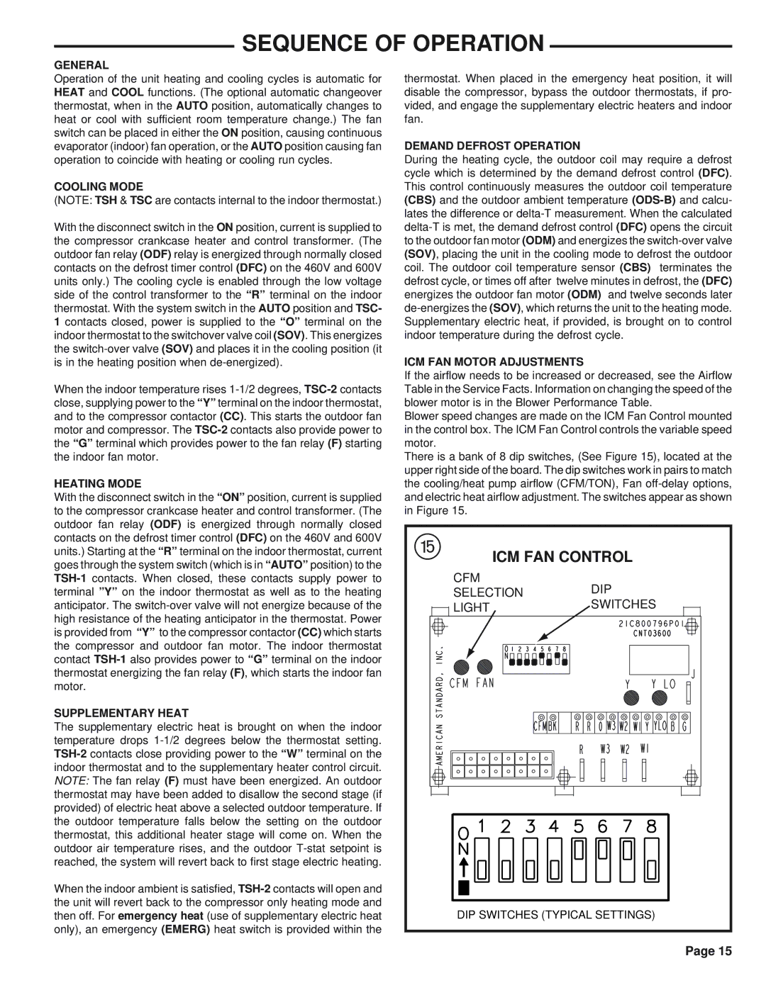
Blower speed changes are made on the ICM Fan Control mounted in the control box. The ICM Fan Control controls the variable speed motor.

There is a bank of 8 dip switches, (See Figure 15), located at the upper right side of the board. The dip switches work in pairs to match the cooling/heat pump airflow (CFM/TON), Fan off-delay options, and electric heat airflow adjustment. The switches appear as shown in Figure 15.

t

ICM FAN CONTROL


CFM

DIP


SELECTION


LIGHT

SWITCHES


DIP SWITCHES (TYPICAL SETTINGS)

Page 15

Page 15
Image 15
Trane WCY030G1, WCY042G1, WCY048G1, WCY036G1, WCY060G1, WCY024G1 manual Sequence of Operation, ICM FAN Control

WCY036G1, WCY042G1, WCY060G1, WCY048G1, WCY030G1 specifications

The Trane WCY series is a line of water-cooled chillers that exemplify innovation and efficiency in commercial HVAC systems. Models such as WCY024G1, WCY030G1, WCY042G1, WCY048G1, and WCY060G1 are designed to meet diverse cooling needs while maintaining energy efficiency and reliability.

One of the standout features of the WCY series is its use of advanced chiller technology, which incorporates a reliable, scroll compressor. These compressors are known for their durability and efficiency, allowing the chillers to provide cooling capacity ranging from 24 to 60 tons, making them suitable for various building sizes and applications. The efficient design of these compressors contributes to lower energy consumption, leading to potential savings on operational costs.

Another significant characteristic of the Trane WCY series is its use of microchannel heat exchangers. These heat exchangers feature a compact design that minimizes refrigerant charge and enhances heat transfer performance. The microchannel technology not only improves overall efficiency, but it also contributes to a smaller physical footprint for the units, allowing for flexible installation options in tight spaces.

The chillers are equipped with advanced controls that optimize performance, enabling users to easily monitor and adjust system operations through a user-friendly interface. The integration of Trane's Tracerâ„¢ control technology enhances operational efficiency by providing real-time data and analytics, which can inform maintenance needs and system adjustments.

In addition to these features, the WCY series includes robust construction that ensures reliability in diverse environments. The units are designed to withstand various weather conditions and are built with corrosion-resistant materials to enhance durability.

Furthermore, the Trane WCY chillers are designed with sustainability in mind. They utilize refrigerants with low global warming potential (GWP), aligning with contemporary environmental standards and enhancing the overall sustainability of building operations.

In summary, the Trane WCY024G1, WCY030G1, WCY048G1, WCY060G1, and WCY042G1 chillers represent cutting-edge technology in water-cooled cooling solutions. With their efficient compressors, innovative heat exchange design, advanced controls, and commitment to sustainability, these chillers are an excellent choice for commercial buildings seeking reliable and efficient cooling solutions. Whether for new installations or retrofits, the Trane WCY series offers versatility and performance that meets the demands of modern HVAC applications.