|
|
|
|
|
|
|
|
|
|
|
|
| Installing |
| ||||||||
• Be certain that the correct mode and wavelength fiber cable is used for single- | CAUTION: Wear a grounding device and observe electrostatic discharge precautions when | |||||||||||||||||||||
mode and/or for multimode fiber cable installations. |
|
|
|
|
|
|
|
|
|
|
| installing Media Converter | ||||||||||
|
|
|
|
|
|
|
|
|
|
|
|
| Failure to observe this caution could result in damage to, and subsequent failure of, the | |||||||||
• Be certain that the | Media Converter |
| ||||||||||||||||||||
|
|
| ||||||||||||||||||||
board is set correctly before installing | NOTE: Media Converter | |||||||||||||||||||||
Center. Cable connections between a hub and the media converter require the | order. |
| ||||||||||||||||||||
To install the Media Converter | ||||||||||||||||||||||
converter and a terminal, transceiver or NIC require the switch to be set to MDI- | ||||||||||||||||||||||
|
|
| ||||||||||||||||||||
X. |
|
|
|
|
|
|
| Set switch |
|
| 1. Remove Media Converter | |||||||||||
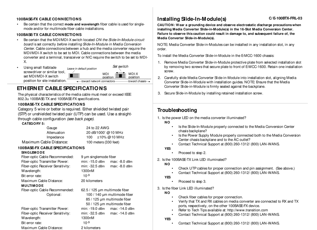
• Using small flatblade | Leave in default position |
|
|
| by removing two screws that secure plate to front of | |||||||||||||||||
screwdriver or similar tool, |
|
|
|
|
|
| MDI |
|
|
|
|
|
|
|
|
|
| screw. |
| |||
|
|
|
|
|
|
|
|
|
|
|
|
|
|
|
|
| ||||||
set |
|
|
|
|
|
| position |
|
|
|
|
|
| position |
| 2. | Carefully slide Media Converter | |||||
|
|
|
|
|
|
|
|
|
|
|
| |||||||||||
position for site installation. |
|
|
|
|
|
|
|
|
|
|
|
|
|
|
|
| ||||||
|
|
|
|
|
| toward network connectors | toward chassis |
|
| Converter | ||||||||||||
|
|
|
|
|
|
|
|
|
|
|
|
|
|
|
|
|
|
|
| |||
ETHERNET CABLE SPECIFICATIONS |
|
|
|
|
|
|
|
|
|
|
|
| Converter |
| ||||||||
|
|
|
|
|
|
|
|
|
|
| 3. | Secure |
| |||||||||
The physical characteristics of the media cable must meet or exceed IEEE |
| |||||||||||||||||||||
|
|
| ||||||||||||||||||||
802.3u |
|
|
|
|
|
|
|
|
|
|
|
|
|
| ||||||||
|
|
|
|
|
|
|
|
|
|
|
|
|
| |||||||||
|
|
|
|
|
|
|
|
|
|
| Troubleshooting |
| ||||||||||
Category 5 wire or better is required. Either shielded twisted pair |
| |||||||||||||||||||||
(STP) or unshielded twisted pair (UTP) can be used. Use a straight- | 1. Is the power LED on the media converter illuminated? |
| ||||||||||||||||||||
through cable configuration (see back page). |
|
|
|
|
|
|
|
|
|
|
|
| ||||||||||
CATEGORY 5: |
|
|
|
|
|
|
|
|
|
|
|
|
|
|
|
|
|
|
| NO |
| |
|
|
|
|
|
|
|
|
|
|
|
|
|
|
|
|
|
|
| • Is the | |||
Gauge |
|
|
|
|
|
| 24 to 22 AWG |
|
|
|
|
|
|
|
|
|
|
|
| |||
|
|
|
|
|
|
|
|
|
|
|
|
|
|
|
|
|
| chasis backplane? |
| |||
Attenuation |
|
|
|
|
|
| 20 dB/1000’ @ 10 MHz |
|
|
|
| |||||||||||
|
|
|
|
|
|
|
|
| • Is the Power Supply Module properly connected both to the Media Conversion | |||||||||||||
Impedance |
|
|
|
|
|
| 100 Ω ±10% @ 10 MHz |
|
|
| ||||||||||||
|
|
|
|
|
|
|
|
| Center chasis backplane and to the AC outlet? |
| ||||||||||||
Maximum Cable Distance: | 100 meters (330 feet) |
|
|
|
| |||||||||||||||||
|
|
| • Contact Technical Support at (800) | |||||||||||||||||||
|
|
|
|
|
|
|
|
|
|
|
|
| ||||||||||
|
|
|
|
|
|
|
|
|
|
|
| YES |
| |||||||||
SINGLEMODE |
|
|
|
|
|
|
|
|
|
|
|
|
|
|
|
|
|
|
| • Proceed to step 2. |
| |
9 µm singlemode fiber |
|
| 2. Is the |
| ||||||||||||||||||
min: | max: |
| ||||||||||||||||||||
| NO |
| ||||||||||||||||||||
min: | max: |
|
| |||||||||||||||||||
| • Check UTP cables for proper connection and pin assignment. (See above.) | |||||||||||||||||||||
Wavelength: |
|
|
|
|
|
| 1300nM |
|
|
|
|
|
|
|
|
|
|
|
| |||
|
|
|
|
|
|
|
|
|
|
|
|
|
|
|
|
|
| • Contact Technical Support at (800) | ||||
Bit error rate: |
|
|
|
|
|
| ≤ |
|
|
|
|
|
|
|
|
|
|
|
| |||
|
|
|
|
|
|
|
|
|
|
|
|
|
|
|
|
|
| YES |
| |||
Maximum Cable Distance: |
|
|
|
|
|
| 20 kilometers |
|
|
|
|
|
|
|
|
|
|
|
|
| ||
|
|
|
|
|
|
|
|
|
|
|
|
|
|
|
|
|
| • Proceed to step 3. |
| |||
MULTIMODE |
|
|
|
|
|
|
|
|
|
|
|
|
|
|
|
|
|
| 3. Is the fiber Link LED illuminated? |
| ||
62.5 / 125 µm multimode fiber |
| |||||||||||||||||||||
| NO |
| ||||||||||||||||||||
Optional: |
|
|
|
|
|
| 100 / 140 µm multimode fiber |
|
| |||||||||||||
|
|
|
|
|
|
| • Check fiber cables for proper connection. |
| ||||||||||||||
|
|
|
|
|
|
| 85 / 125 µm multimode fiber |
|
| |||||||||||||
|
|
|
|
|
|
|
| • Verify that TX and RX cables on media converter are connected to RX and TX | ||||||||||||||
|
|
|
|
|
|
| 50 / 125 µm multimode fiber |
| ||||||||||||||
|
|
|
|
|
|
|
| ports, respectively, on the other |
| |||||||||||||
min: | max: |
|
| |||||||||||||||||||
| • Refer to Tech Tips available at: http://www.transition.com |
| ||||||||||||||||||||
min: | max: |
|
| |||||||||||||||||||
| • Contact Technical Support at (800) | |||||||||||||||||||||
Wavelength: |
|
|
|
|
|
| 1300nM |
|
|
|
|
|
|
|
|
|
|
|
| |||
|
|
|
|
|
|
|
|
|
|
|
|
|
|
|
|
|
| YES |
| |||
Bit error rate: |
|
|
|
|
|
| ≤ |
|
|
|
|
|
|
|
|
|
|
|
| • Contact Technical Support at (800) | ||
Maximum Cable Distance: |
|
|
|
|
|
| 2 kilometers |
|
|
|
|
|
|
|
|
|
|
|
|
|
| |