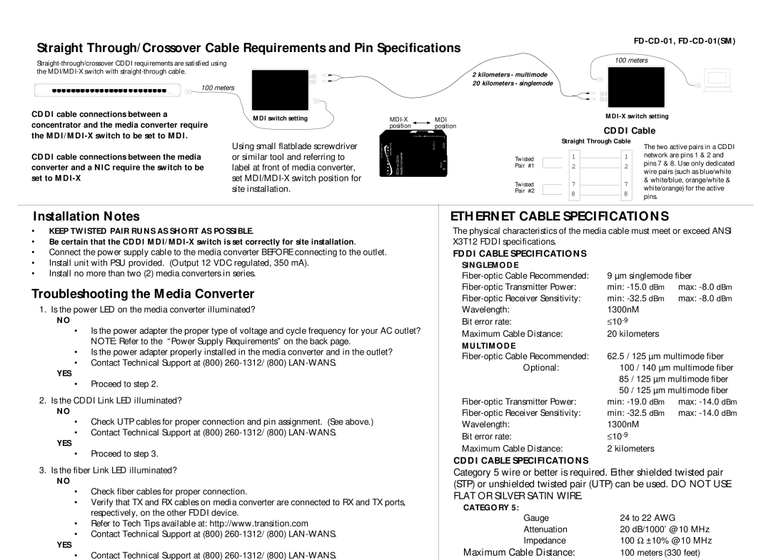
Straight Through/Crossover Cable Requirements and Pin Specifications
100 meters
2 kilometers - multimode
20 kilometers - singlemode
FD-CD-01, FD-CD-01(SM)
100 meters
CDDI cable connections between a concentrator and the media converter require the
MDI switch setting
position position
CDDI Cable
CDDI cable connections between the media converter and a NIC require the switch to be set to
Using small flatblade screwdriver or similar tool and referring to label at front of media converter, set
| MDI |
| |
Input |
| CDDI | |
12V DC | FDDI to CDDI |
| FDDI |
Twisted Pair #1
Twisted Pair #2
Straight Through Cable
11
22
77
88
The two active pairs in a CDDI network are pins 1 & 2 and pins 7 & 8. Use only dedicated wire pairs (such as blue/white & white/blue, orange/white & white/orange) for the active pins.
Installation Notes
•KEEP TWISTED PAIR RUNS AS SHORT AS POSSIBLE.
•Be certain that the CDDI
•Connect the power supply cable to the media converter BEFORE connecting to the outlet.
•Install unit with PSU provided. (Output 12 VDC regulated, 350 mA).
•Install no more than two (2) media converters in series.
Troubleshooting the Media Converter
1.Is the power LED on the media converter illuminated?
NO
•Is the power adapter the proper type of voltage and cycle frequency for your AC outlet? NOTE: Refer to the “Power Supply Requirements” on the back page.
•Is the power adapter properly installed in the media converter and in the outlet?
•Contact Technical Support at (800)
YES
•Proceed to step 2.
2.Is the CDDI Link LED illuminated?
NO
•Check UTP cables for proper connection and pin assignment. (See above.)
•Contact Technical Support at (800)
YES
•Proceed to step 3.
3.Is the fiber Link LED illuminated?
NO
•Check fiber cables for proper connection.
•Verify that TX and RX cables on media converter are connected to RX and TX ports, respectively, on the other FDDI device.
•Refer to Tech Tips available at: http://www.transition.com
•Contact Technical Support at (800)
YES
•Contact Technical Support at (800)
ETHERNET CABLE SPECIFICATIONS
The physical characteristics of the media cable must meet or exceed ANSI X3T12 FDDI specifications.
FDDI CABLE SPECIFICATIONS
SINGLEMODE |
|
|
9 µm singlemode fiber | ||
min: | max: | |
min: | max: | |
Wavelength: | 1300nM |
|
Bit error rate: | ≤ |
|
Maximum Cable Distance: | 20 kilometers |
|
MULTIMODE |
|
|
62.5 / 125 µm multimode fiber | ||
Optional: | 100 / 140 µm multimode fiber | |
| 85 / 125 µm multimode fiber | |
| 50 / 125 µm multimode fiber | |
min: | max: | |
min: | max: | |
Wavelength: | 1300nM |
|
Bit error rate: | ≤ |
|
Maximum Cable Distance: | 2 kilometers |
|
CDDI CABLE SPECIFICATIONS
Category 5 wire or better is required. Either shielded twisted pair (STP) or unshielded twisted pair (UTP) can be used. DO NOT USE FLAT OR SILVER SATIN WIRE.
CATEGORY 5: |
|
Gauge | 24 to 22 AWG |
Attenuation | 20 dB/1000’ @ 10 MHz |
Impedance | 100 Ω ±10% @ 10 MHz |
Maximum Cable Distance: | 100 meters (330 feet) |