Transition Networks SPS-48V instruction manual Maintenance, Replacing Power Supply Module Fuse

Models: SPS-48V

1 4
Download 4 pages 44.11 Kb
Page 4
Image 4
MAINTENANCE

MAINTENANCE

Replacing Power Supply Module Fuse

CAUTION: Wear a grounding device and observe electrostatic discharge precautions when replacing the fuse in the 48-to-12 VDC External Power Supply. Failure to observe this caution could result in damage to, and subsequent failure of, the 48-to-12 VDC External Power Supply.

CAUTION: Replace fuse only with same size and rating. Failure to observe this caution could result in equipment damage.

CAUTION: Ensure that power source is NOT powered when disconnecting power from, or connecting power to, the 48-to-12 External Power Supply. Failure to observe this caution could result in damage to, and subsequent failure of, the 48-to-12 External Power Supply and of any attached device.

1.Ensure that external power source is powered OFF.

2.Disconnect +48-VDC terminal from Media Conversion Center terminal block control marked “+” by turning terminal screw counter-clockwise.

3.Disconnect -48-VDC terminal from Media Conversion Center terminal block control marked “-” by turning terminal screw counter-clockwise.

4.Disconnect ground terminal from Media Conversion Center terminal block control marked “chassis ground” by turning terminal screw counter-clockwise.

5.Remove and retain four (4) screws that secure cover to External Power Supply.

6.Carefully lift cover from External Power Supply.
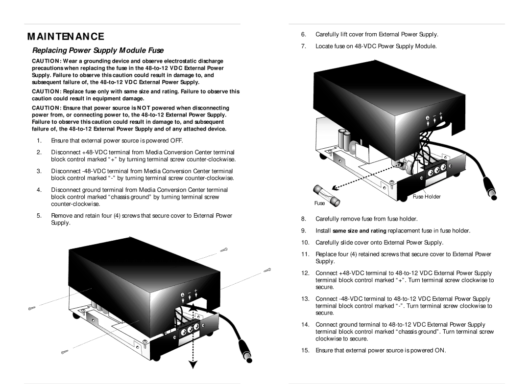
7.Locate fuse on 48-VDC Power Supply Module.

Fuse Holder

Fuse

8.Carefully remove fuse from fuse holder.

9.Install same size and rating replacement fuse in fuse holder.

10.Carefully slide cover onto External Power Supply.

11.Replace four (4) retained screws that secure cover to External Power Supply.

12.Connect +48-VDC terminal to 48-to-12 VDC External Power Supply terminal block control marked “+”. Turn terminal screw clockwise to secure.

13.Connect -48-VDC terminal to 48-to-12 VDC External Power Supply terminal block control marked “-”. Turn terminal screw clockwise to secure.

14.Connect ground terminal to 48-to-12 VDC External Power Supply terminal block control marked “chassis ground”. Turn terminal screw clockwise to secure.

15.Ensure that external power source is powered ON.

Page 4
Image 4
Transition Networks SPS-48V instruction manual Maintenance, Replacing Power Supply Module Fuse