II. RECEIPT INSPECTION | III. INSTALLATION (continued) |
All Traulsen products are factory tested for performance and are free from defects when shipped. The utmost care has been taken in crating this product to protect against damage in transit.
You should carefully inspect your unit for damage during delivery. If damage is detected, you should save all the crating materials and make note on the carrier’s Bill Of Lading describing the damage. A freight claim should be filed immediately. If damage is subsequently noted dur- ing or immediately after installation, contact our customer care team to file a freight claim. There is a fifteen (15) day limit to file freight damage with the carrier. Under no condition may a damaged unit be returned to Traulsen without first obtaining written permission (return autho- rization). You may contact Hobart/Traulsen customer care at
III.INSTALLATION
III.a - LOCATION:
Select a proper location for your unit, away from extreme heat or cold.
III.b - PACKAGING:
Your Traulsen unit is shipped from the factory bolted to a sturdy wooden pallet in stretch wrapped material.
Most exterior stainless steel surfaces have a protective vinyl covering to prevent scratching during manufactur- ing, shipping and installation. After the unit is installed in place of application peel, remove and discard the covering from all surfaces.
To remove the wooden pallet, first if at all possible, we suggest that the cabinet remain bolted to the pallet dur- ing all transportation to the point of final installation. The bolts can then be removed with a 1/2” socket wrench. Avoid laying the unit on its back for removal of the pallet.
NOTE: Traulsen does not recommend laying the unit on its back. If you must, please allow the unit to re- main in an upright position for 24 hours before plug- ging it in so that the compressor oils and refrigerant may settle.
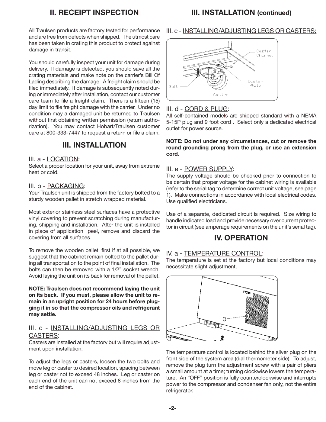
III.c - INSTALLING/ADJUSTING LEGS OR
CASTERS:
Casters are installed at the factory but will require adjust- ment upon installation.
To adjust the legs or casters, loosen the two bolts and move leg or caster to desired location, spacing between leg or caster not to exceed 48 inches. Leg or caster on each end of the unit can not exceed 8 inches from the end of the cabinet.
III.c - INSTALLING/ADJUSTING LEGS OR CASTERS:
III.d - CORD & PLUG:
All
NOTE: Do not under any circumstances, cut or remove the round grounding prong from the plug, or use an extension cord.
III.e - POWER SUPPLY:
The supply voltage should be checked prior to connection to be certain that proper voltage for the cabinet wiring is available (refer to the serial tag to determine correct unit voltage, see page 1). Make connections in accordance with local electrical codes. Use qualified electricians.
Use of a separate, dedicated circuit is required. Size wiring to handle indicated load and provide necessary over current protec- tor in circuit (see amperage requirements on the unit’s serial tag).
IV. OPERATION
IV. a - TEMPERATURE CONTROL:
The temperature is set at the factory but local conditions may necessitate slight adjustment.
The temperature control is located behind the silver plug on the front side of the system area (dial thermometer side). To adjust, remove the plug turn the adjustment screw with a pair of pliers a small amount at a time; turning clockwise lowers the tempera- ture. An “OFF” position is fully counterclockwise and interrupts power to the compressor and condenser fan only, not the entire refrigerator.