III. INSTALLATION (continued)
III.i - OPTIONAL UTILITY BASE (cont'd):
3.Assemble four 1/2
4.Place rear cover on back of utility base so
5.Install front grill on front of stacking base with eight 8 – 18
If your unit comes with a utility base, we recommend securing the base to the floor. Place the unit in its final installed position, then apply a bead of NSF approved silicone sealant around the bottom.
III.j - OPTIONAL STACKING KIT:
Models UHT27 and ULT27 only have the option of a stacking kit, in which no more than two (2) units can be stacked one on top of the other.
1.Install legs, casters or utility base on bottom unit following instructions elsewhere in this manual. Place bottom unit near final installed location leaving access to rear for further assembly.
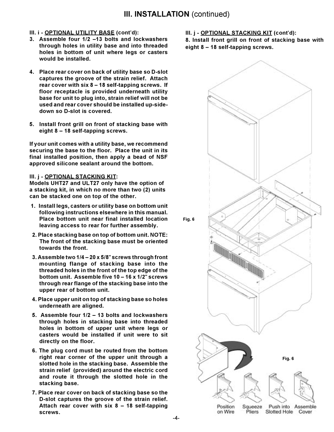
2.Place stacking base on top of bottom unit. NOTE: The front of the stacking base must be oriented towards the front.
3.Assemble two 1/4 – 20 x 5/8" screws through front mounting flange of stacking base into the threaded holes in the front of the top edge of the bottom unit. Assemble five 10 – 16 x 1/2" screws through rear flange of the stacking base into the upper rear of bottom unit.
4.Place upper unit on top of stacking base so holes underneath are aligned.
5.Assemble four 1/2 – 13 bolts and lockwashers through holes in stacking base into threaded holes in bottom of upper unit where legs or casters would be installed if unit were to sit directly on the floor.
6.The plug cord must be routed from the bottom right rear corner of the upper unit through a slotted hole in the stacking base. Assemble the strain relief (provided) around the electric cord and route it through the slotted hole in the stacking base.
7.Place rear cover on back of stacking base so the
III.j - OPTIONAL STACKING KIT (cont'd):
8.Install front grill on front of stacking base with eight 8 – 18
Fig. 6
Fig. 6