III. INSTALLATION (continued)
III.c - INSTALLING LEGS OR CASTERS (cont'd):
Please note that Traulsen units are not designed to be moved while on legs. If the unit requires moving, a pallet jack or forklift should be used to prevent damage.
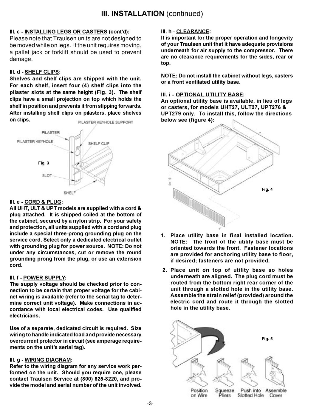
III.d - SHELF CLIPS:
Shelves and shelf clips are shipped with the unit. For each shelf, insert four (4) shelf clips into the pilaster slots at the same height (Fig. 3). The shelf clips have a small projection on top which holds the shelf in position and prevents it from slipping forwards. After installing shelf clips on pilasters, place shelves on clips.
III.h - CLEARANCE:
It is important for the proper operation and longevity of your Traulsen unit that it have adequate provisions underneath for air supply to the compressor. There are no clearance requirements for the sides, rear or top.
NOTE: Do not install the cabinet without legs, casters or a front ventilated utility base.
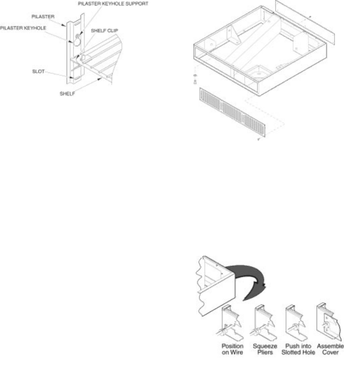
III.i - OPTIONAL UTILITY BASE:
An optional utility base is available, in lieu of legs or casters, for models UHT27, ULT27, UPT276 & UPT279 only. To install this, follow the directions below see (figure 4):
Fig. 3
III.e - CORD & PLUG:
All UHT, ULT & UPT models are supplied with a cord & plug attached. It is shipped coiled at the bottom of the cabinet, secured by a nylon strip. For your safety and protection, all units supplied with a cord and plug include a special
III.f - POWER SUPPLY:
The supply voltage should be checked prior to con- nection to be certain that proper voltage for the cabi- net wiring is available (refer to the serial tag to deter- mine correct unit voltage). Make connections in ac- cordance with local electrical codes. Use qualified electricians.
Use of a separate, dedicated circuit is required. Size wiring to handle indicated load and provide necessary overcurrent protector in circuit (see amperage require- ments on the unit’s serial tag).
III.g - WIRING DIAGRAM:
Refer to the wiring diagram for any service work per- formed on the unit. Should you require one, please contact Traulsen Service at (800)
Fig. 4
1.Place utility base in final installed location. NOTE: The front of the utility base must be oriented towards the front. Fastener locations are provided for anchoring utility base to floor, if desired; fasteners are not provided.
2.Place unit on top of utility base so holes underneath are aligned. The plug cord must be routed from the bottom right rear corner of the unit through a slotted hole in the utility base. Assemble the strain relief (provided) around the electric cord and route it through the slotted hole in the utility base.
Fig. 5