
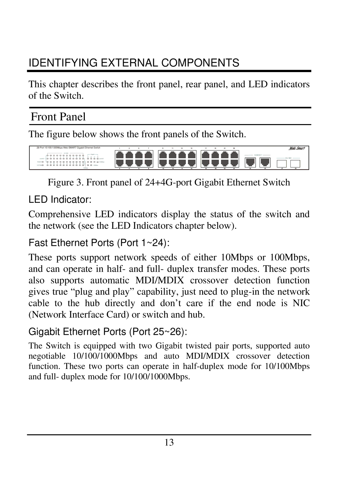
21000BASE-T, 2410/100BASE-TX specifications
TRENDnet, a renowned name in networking and connectivity solutions, offers a range of products including the TRENDnet 21000BASE-T and 2410/100BASE-TX. These products are designed to meet the ever-growing demands for high-speed networking in both residential and commercial environments.The TRENDnet 21000BASE-T is built to accommodate bandwidth-intensive applications. It features support for 10G Ethernet, allowing data rates of up to 10 Gbps over standard Cat 6 cabling, making it a suitable choice for organizations looking to future-proof their networks. One of its standout features is its ability to enhance network reliability. With advanced technologies such as Auto Negotiation and Automatic MDI/MDI-X crossover, the device can automatically detect the necessary configurations for optimal connectivity, thus simplifying installation and reducing errors.
On the other hand, the TRENDnet 2410/100BASE-TX caters to users who require a more basic solution for their networking needs. This model supports Ethernet data rates of 10/100 Mbps, making it ideal for less demanding applications yet still highly efficient in delivering consistent network performance. One of its defining characteristics is its Plug and Play feature, which enables straightforward setup without the need for complex configuration. The 2410/100BASE-TX is particularly effective in supporting office networks where multiple devices need to connect seamlessly.
Both products incorporate robust security features essential for protecting sensitive data in today’s networks. TRENDnet’s networking equipment often comes equipped with VLAN support, enabling user segmentation and enhanced data security. Furthermore, these devices are designed with energy efficiency in mind, adhering to the IEEE 802.3az Energy-Efficient Ethernet standard, which helps reduce power consumption during periods of low activity.
Additionally, TRENDnet ensures compatibility across a wide range of operating systems and network configurations. This flexibility allows businesses to integrate their existing infrastructure without needing significant upgrades.
In conclusion, the TRENDnet 21000BASE-T and 2410/100BASE-TX provide versatile and reliable networking solutions suitable for various environments. With their impressive speed, easy deployment features, and enhanced security measures, these products exemplify TRENDnet's commitment to delivering high-quality networking technology to meet modern demands.