Warranty today Tripp |
| |||
Registration:online | for | a | Lite | |
.com/warranty | ||||
| FREE |
|
| |
register | .tripplite |
|
| |
win |
|
|
| |
to |
|
|
| |
www |
|
|
| |
chance |
|
|
|
|
— |
|
|
|
|
product |
|
|
|
|
Owner's Manual Addendum
BP12V81
Battery Pack Connection
This addendum deals solely with the procedure to connect a BP12V81 Battery Pack to an Inverter/Charger. Follow all safety warnings and instructions
included separately with the Battery Pack and Inverter/Charger prior to attempting connection.
Step 1
Place the Battery Pack close enough to the Inverter/Charger so that the Battery Pack's cables can reach.
Step 2
Place the Inverter/Charger's operating mode switch in the "OFF" position. Make sure the Inverter/Charger is unplugged from and/or not receiving power from any AC source. Make sure the Inverter/Charger is disconnected from any DC power source.
Step 3
Remove the
WARNING!
Failure to observe proper polarity dur- ing connection could damage and void the warranties of both the BP12V81 Battery Pack and the Inverter/Charger.
Securely tighten the Inverter/Charger's DC terminals to prevent the red battery connector's wires from coming loose due to accidental stress or tension.
Step 4
Take the Inverter/Charger's red battery connector (A) and connect it to the red battery connector located at the end of the longer of the two cables on the BP12V81 Battery Pack (B).* The two connectors can only be joined with one orientation and should snap into posi- tion when pressure is applied.
* Note: There are two cables located on the Battery
Pack: a long cable and a short cable. The long cable is for connecting to the Inverter/Charger (or to an additional Battery Pack in an optional
Step 5
Restore AC power to the Inverter/Charger. The BP12V81 Battery Pack(s) and Inverter/Charger are now connected and ready to be used for battery backup applications.
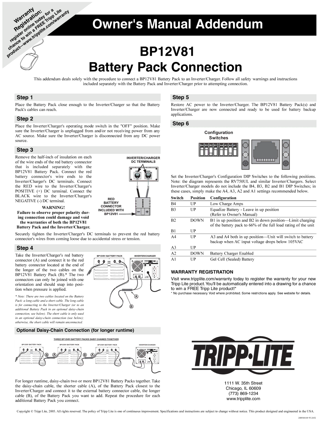
Step 6
Configuration
Switches
B4 | B3 B2 B1 | A4 A3 A2 A1 |
Set the Inverter/Charger's Configuration DIP Switches to the following positions. Note: the diagram represents the RV750UL and similar Inverter/Chargers. Select Inverter/Charger models do not include the B4, B3, B2 and B1 DIP Switches; in these cases, simply make the A4, A3, A2 and A1 settings recommended below.
Switch | Position | Configuration |
B4 | UP | Low Charge Amps |
B3 | UP | Equalize Battery - Leave in up position |
|
| (Refer to Owner's Manual) |
B2 | DOWN | B1 in up position and B2 in down |
|
| of the battery pack to 66% of the full load rating of the unit |
B1 | UP |
|
A4 | UP | A3 and A4 both in up |
|
| backup when AC input voltage drops below 105VAC |
A3 | UP |
|
A2 | DOWN | Battery Charger Enabled |
A1 | UP | Gel Cell (Sealed) Battery |
WARRANTY REGISTRATION
Visit www.tripplite.com/warranty today to register the warranty for your new Tripp Lite product. You'll be automatically entered into a drawing for a chance to win a FREE Tripp Lite product!*
* No purchase necessary. Void where prohibited. Some restrictions apply. See website for details.
Optional Daisy-Chain Connection (for longer runtime)
THREE BP12V81 BATTERY PACKS DAISY CHAINED TOGETHER
BP12V81 BATTERY PACK | BP12V81 BATTERY PACK | BP12V81 BATTERY PACK | INVERTER/CHARGER | ||||||
|
|
|
|
|
|
|
|
|
|
|
|
|
|
|
|
|
|
|
|
|
|
|
|
|
|
|
|
|
|
B A 
 B A
B A
For longer runtime,
1111 W. 35th Street Chicago, IL 60609
(773)
Copyright © Tripp Lite, 2005. All rights reserved. The policy of Tripp Lite is one of continuous improvement. Specifications and instructions are subject to change without notice. This product designed and engineered in the USA.
200504148