Installation
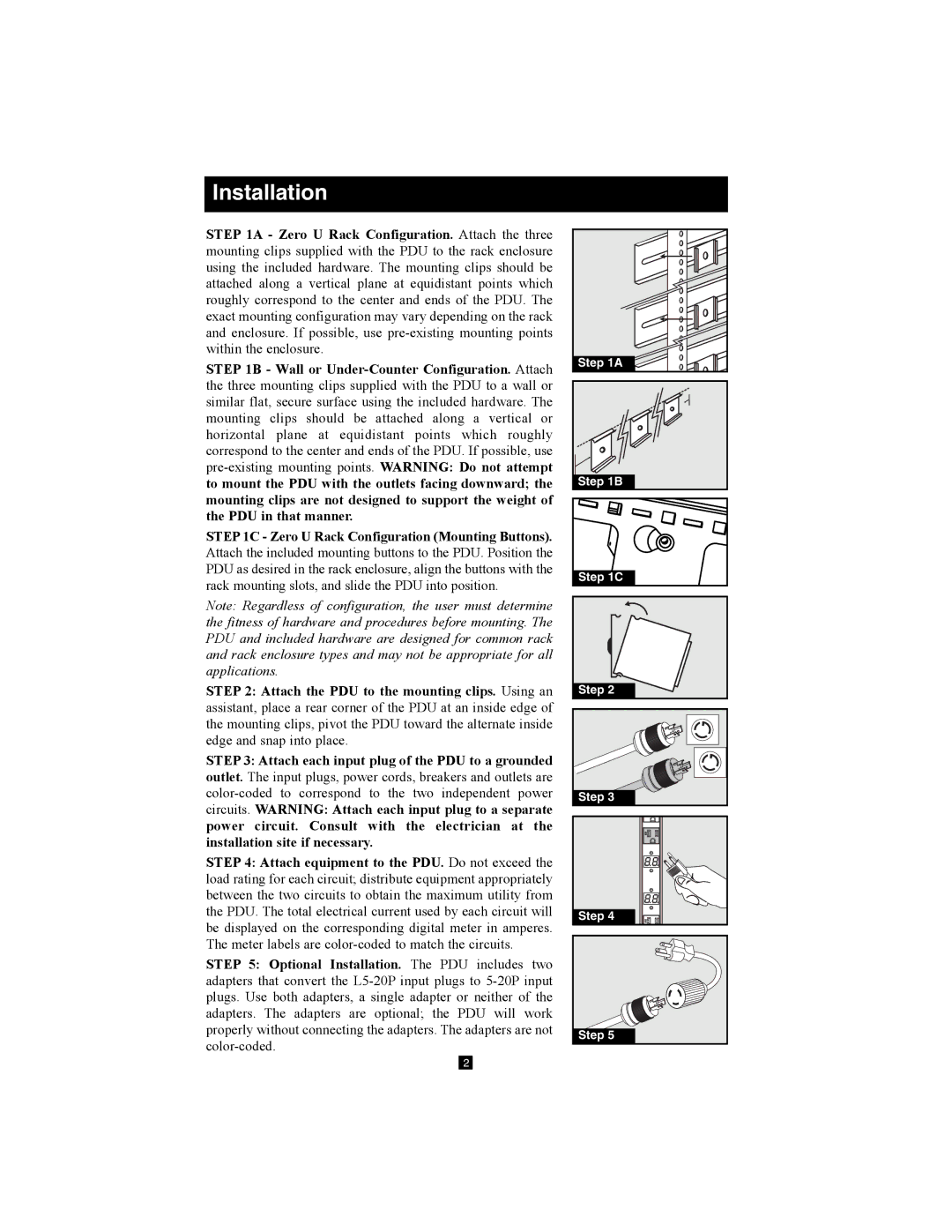
STEP 1A - Zero U Rack Configuration. Attach the three mounting clips supplied with the PDU to the rack enclosure using the included hardware. The mounting clips should be attached along a vertical plane at equidistant points which roughly correspond to the center and ends of the PDU. The exact mounting configuration may vary depending on the rack and enclosure. If possible, use
STEP 1B - Wall or
STEP 1C - Zero U Rack Configuration (Mounting Buttons). Attach the included mounting buttons to the PDU. Position the PDU as desired in the rack enclosure, align the buttons with the rack mounting slots, and slide the PDU into position.
Note: Regardless of configuration, the user must determine the fitness of hardware and procedures before mounting. The PDU and included hardware are designed for common rack and rack enclosure types and may not be appropriate for all applications.
STEP 2: Attach the PDU to the mounting clips. Using an assistant, place a rear corner of the PDU at an inside edge of the mounting clips, pivot the PDU toward the alternate inside edge and snap into place.
STEP 3: Attach each input plug of the PDU to a grounded outlet. The input plugs, power cords, breakers and outlets are
STEP 4: Attach equipment to the PDU. Do not exceed the load rating for each circuit; distribute equipment appropriately between the two circuits to obtain the maximum utility from the PDU. The total electrical current used by each circuit will be displayed on the corresponding digital meter in amperes. The meter labels are
STEP 5: Optional Installation. The PDU includes two adapters that convert the
Step 1A
Step 1B |
Step 1C
Step 2
Step 3 |
Step 4
Step 5 |
2