Rackmount Power Strips and Isobar Rackmount Surge Suppressors/ Line-Noise Filters specifications
Tripp Lite, a leading provider of power protection and connectivity solutions, offers an impressive range of rackmount power strips and Isobar rackmount surge suppressors/line-noise filters. These products are essential for any organization that demands reliable and efficient power management in their data centers, server rooms, or telecommunications setups.One of the standout features of Tripp Lite rackmount power strips is their robust construction. Built to be durable, these power strips are designed to withstand the rigors of everyday use in professional environments. They come with multiple outlets to accommodate a variety of devices, ensuring that all critical equipment can be powered simultaneously. With a wide range of configurations available, users can select the ideal model to match their specific power requirements.
In terms of technology, Tripp Lite employs advanced components in their Isobar rackmount surge suppressors. Each Isobar unit is equipped with high joule ratings, which means they can absorb a significant amount of energy from electrical surges, protecting vital equipment from damage. The surge suppressors also feature noise filtering capabilities, which reduce electromagnetic interference (EMI) and radio frequency interference (RFI). This is particularly important in data processing environments, where even minor fluctuations can cause data corruption or performance degradation.
Tripp Lite's surge suppressors incorporate a patented isolating filter technology. This isolation effectively prevents interference between connected devices, ensuring cleaner power delivery. Each unit includes a resettable circuit breaker that provides overload protection, enhancing overall safety during operation.
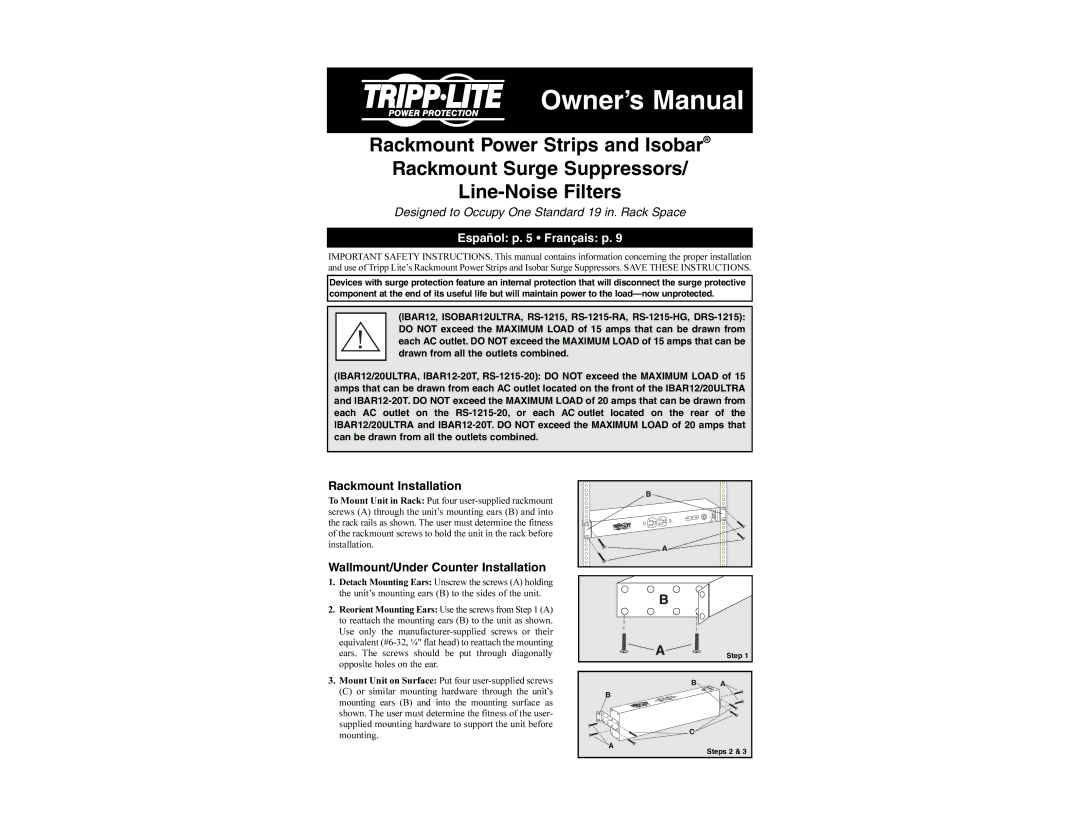
Another key characteristic of Tripp Lite power strips and surge suppressors is their compliance with industry standards. Many models meet or exceed UL 1449 surge suppression testing standards, which assures users of their reliability. Additionally, Tripp Lite offers models with vertical and horizontal mounting options, making installation flexible according to rack configuration.
To further enhance user experience, many of these power strips and surge protectors come with LED status indicators that provide real-time feedback on power availability and surge protection status. This feature is especially beneficial for quickly identifying potential issues within power management systems.
In conclusion, Tripp Lite rackmount power strips and Isobar surge suppressors/line-noise filters are essential tools for any enterprise that values robust power management. With their durable construction, cutting-edge technology, and focus on safety, these products deliver the reliability and performance necessary to keep critical systems running smoothly.