3 – SRCABLETRAY Installation
Note: You can remove the roof panel to aid installation, but this step is not required.
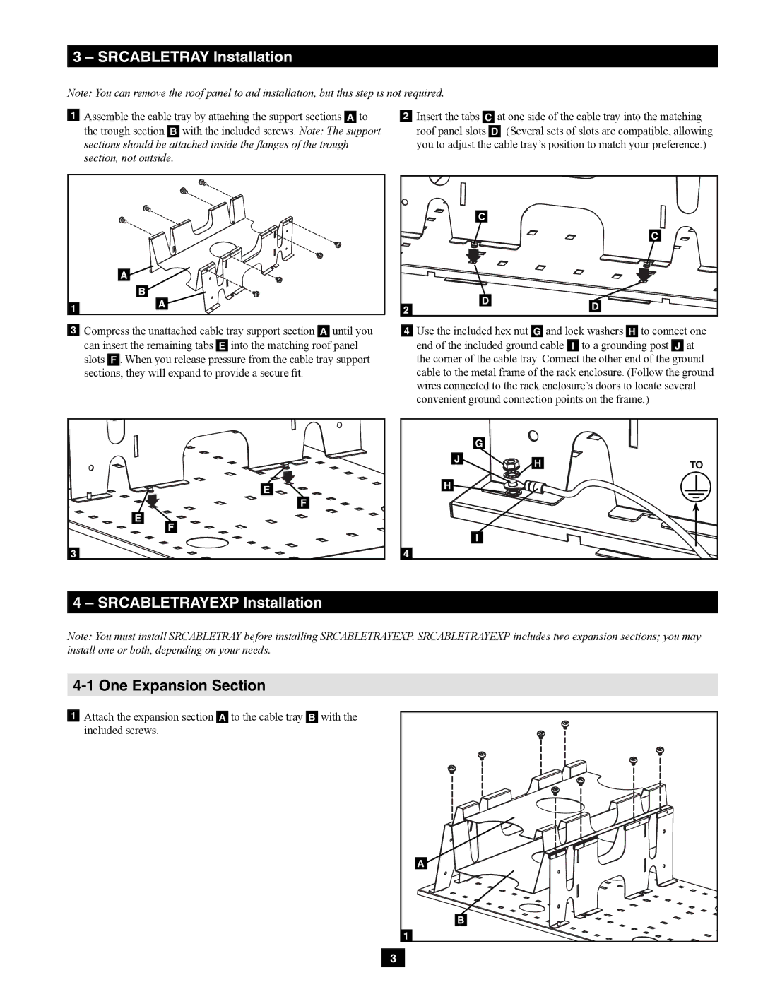
![]() Assemble the cable tray by attaching the support sections
Assemble the cable tray by attaching the support sections ![]() to the trough section
to the trough section ![]() with the included screws. Note: The support sections should be attached inside the flanges of the trough section, not outside.
with the included screws. Note: The support sections should be attached inside the flanges of the trough section, not outside.
![]() Insert the tabs
Insert the tabs ![]() at one side of the cable tray into the matching roof panel slots
at one side of the cable tray into the matching roof panel slots ![]() . (Several sets of slots are compatible, allowing you to adjust the cable tray’s position to match your preference.)
. (Several sets of slots are compatible, allowing you to adjust the cable tray’s position to match your preference.)
A |
B |
A |
![]() Compress the unattached cable tray support section
Compress the unattached cable tray support section ![]() until you can insert the remaining tabs
until you can insert the remaining tabs ![]() into the matching roof panel slots
into the matching roof panel slots ![]() . When you release pressure from the cable tray support sections, they will expand to provide a secure fit.
. When you release pressure from the cable tray support sections, they will expand to provide a secure fit.
| C |
|
|
| C |
2 | D | D |
| ||
|
|
![]() Use the included hex nut
Use the included hex nut ![]() and lock washers
and lock washers ![]() to connect one end of the included ground cable
to connect one end of the included ground cable ![]() to a grounding post
to a grounding post ![]() at the corner of the cable tray. Connect the other end of the ground cable to the metal frame of the rack enclosure. (Follow the ground wires connected to the rack enclosure’s doors to locate several convenient ground connection points on the frame.)
at the corner of the cable tray. Connect the other end of the ground cable to the metal frame of the rack enclosure. (Follow the ground wires connected to the rack enclosure’s doors to locate several convenient ground connection points on the frame.)
E |
F |
E |
F |
| G |
|
J | H | TO |
| ||
H |
|
|
| I |
|
4 – SRCABLETRAYEXP Installation
Note: You must install SRCABLETRAY before installing SRCABLETRAYEXP. SRCABLETRAYEXP includes two expansion sections; you may install one or both, depending on your needs.
4-1 One Expansion Section
![]() Attach the expansion section
Attach the expansion section ![]() to the cable tray
to the cable tray ![]() with the included screws.
with the included screws.
A |
B |
3