Section
2Assembly
WARNING
To prevent personal injury or property damage, do not start the engine until all assembly steps are complete and you have read and understand the safety and operating instruc- tions in this manual.
Introduction
Carefully follow these assembly steps to correctly prepare your tiller for use. It is recommended that you read this Section in its entirety before beginning assembly.
Inspect unit
Inspect the unit and carton for damage immediately after delivery. Contact the carrier (trucking company) if you find or suspect damage. Inform them of the damage and request instructions for filing a claim. To protect your rights, put your claim in writing and mail a copy to the carrier within 15 days after the unit has been delivered. Contact us at the factory if you need assistance in this matter.
STEP 1: Unpacking Instructions
1.Remove any cardboard inserts and packaging material from the carton. Remove any staples from the bottom of the carton and then lift the carton up and off the unit.
2. The tiller is heavy and you should not attempt to remove it from the shipping platform until the handlebars are installed. The procedure for removing the tiller is explained in Step 3 of these assembly steps. NOTE: Be careful not to severely bend any of the control cables on the unit.
3.Remove all unassembled parts and the separate hardware bag from the
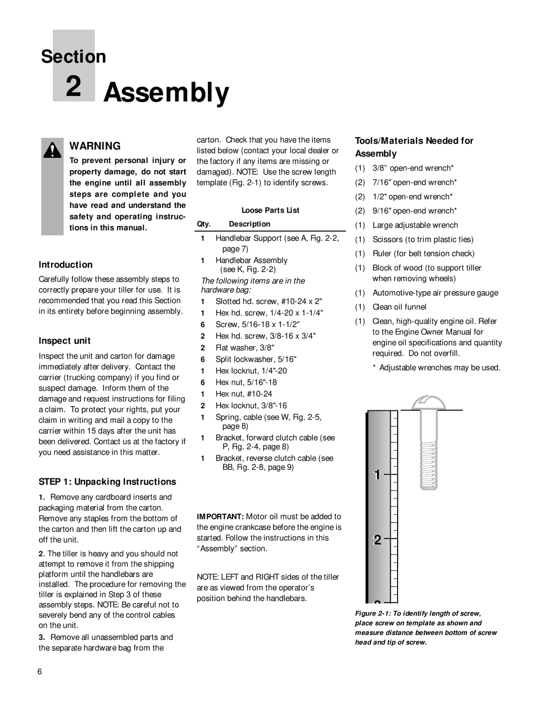
carton. Check that you have the items listed below (contact your local dealer or the factory if any items are missing or damaged). NOTE: Use the screw length template (Fig.
Loose Parts List
Qty. Description
1Handlebar Support (see A, Fig.
1Handlebar Assembly (see K, Fig.
The following items are in the hardware bag:
1Slotted hd. screw,
1Hex hd. screw,
6Screw,
2Hex hd. screw,
2Flat washer, 3/8"
6Split lockwasher, 5/16"
1Hex locknut,
6Hex nut,
1Hex nut,
2Hex locknut,
1Spring, cable (see W, Fig.
1Bracket, forward clutch cable (see P, Fig.
1Bracket, reverse clutch cable (see BB, Fig.
IMPORTANT: Motor oil must be added to the engine crankcase before the engine is started. Follow the instructions in this “Assembly” section.
NOTE: LEFT and RIGHT sides of the tiller are as viewed from the operator’s position behind the handlebars.
Tools/Materials Needed for Assembly
(1)3/8”
(2)7/16"
(2) 1/2"
(2) 9/16"
(1) Large adjustable wrench
(1) Scissors (to trim plastic ties)
(1) Ruler (for belt tension check)
(1)Block of wood (to support tiller when removing wheels)
(1)
(1) Clean oil funnel
(1)Clean,
*Adjustable wrenches may be used.
1 |
2 |
3 |
Figure 2-1: To identify length of screw, place screw on template as shown and measure distance between bottom of screw head and tip of screw.
6