Section 2: Assembly
STEP 5: Install Reverse Clutch Cable
1.Remove the two
2.Unwrap the reverse clutch cable (the cable with a knob and a large hex nut attached to it) from around its shipping position and route the cable (CC, Fig.
3.Insert the cable up through the slot in
the cable bracket and position the threaded assembly as shown in Fig.
AA |
|
BB | AA |
| |
DD |
|
CC |
|
| Flat Side |
Fig. 2-8: Install reverse cable bracket and reverse clutch cable.
CC
EE
Fig. 2-9: Route reverse clutch cable (CC) as shown. Attach with cable tie (EE).
4.Fasten the reverse clutch cable to the left side handlebar with a cable tie (EE, Fig.
5.Test the function of the reverse clutch cable by pulling the knob out and releasing it. The knob should return to its neutral position (resting against bracket) when it is released. If it doesn’t, contact your local dealer or the factory for technical assistance.
STEP 6: Check Level of
Transmission Gear Oil
The transmission was filled with gear oil at the factory. However, you should check the gear oil level to make certain it is correct.
IMPORTANT: Do not operate the tiller if the gear oil level is low. Doing so will result in severe damage to the transmis- sion components.
1.Put the tiller on level ground. Pull the Depth Regulator Lever (FF, Fig.
2.Remove the oil fill plug (GG, Fig.
3.The gear oil level is correct if the gear oil is approximately halfway up the side of the drive shaft.
4.If the gear oil level is low, add gear oil by referring to “A. To Check the Transmis- sion Gear Oil Level” in Section 5.
STEP 7: Add Motor Oil to Engine
The tiller is shipped without oil in the engine.
IMPORTANT: Do not start the engine without first adding motor oil. Severe engine damage will result if the engine is run without oil.
1.Refer to the Engine Owner’s Manual (supplied with tiller) for engine oil specifi- cations and capacities.
2.With the tiller on level ground, pull the Depth Regulator Lever (FF, Fig.
3.Add motor oil as described in the Engine Owner’s Manual.
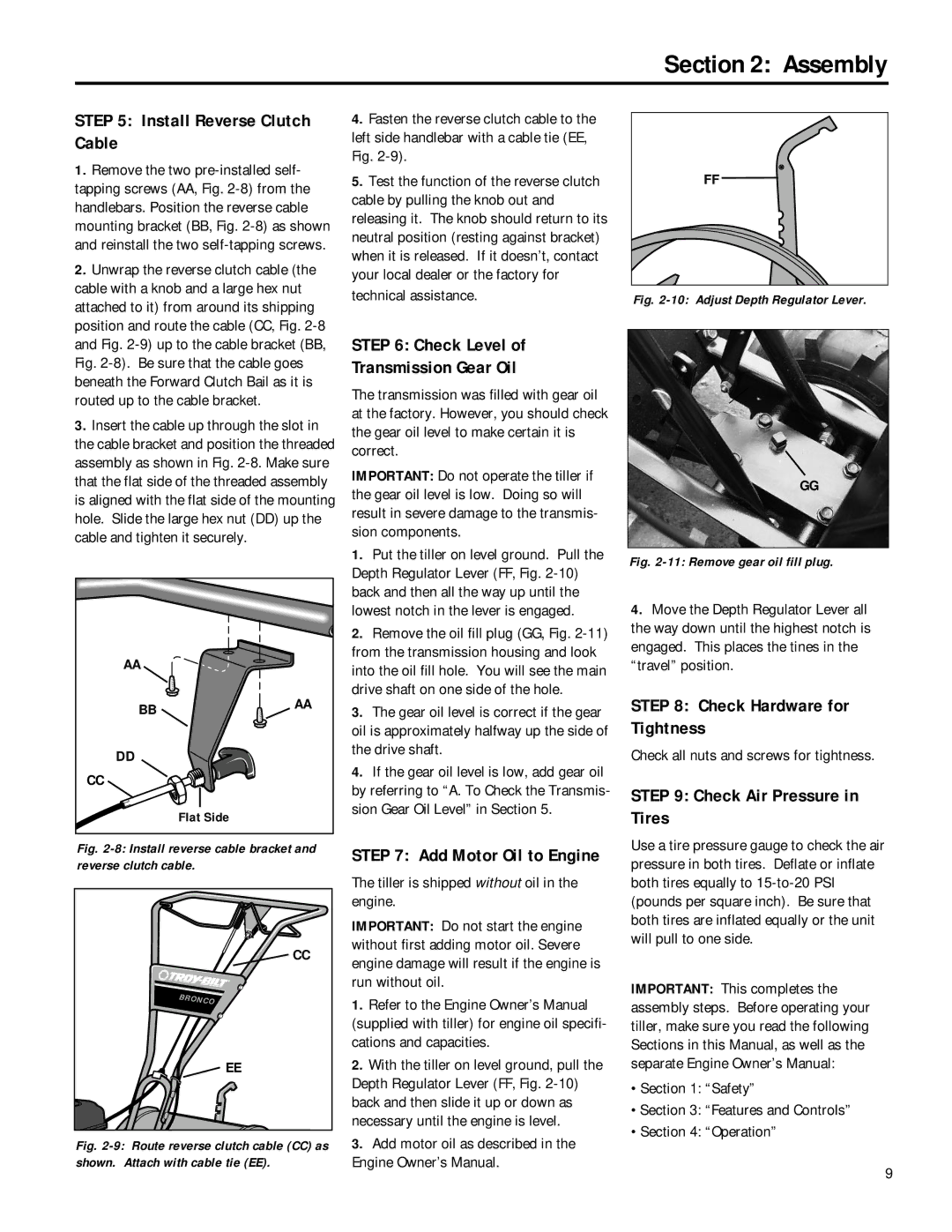
FF
Fig. 2-10: Adjust Depth Regulator Lever.
GG
Fig. 2-11: Remove gear oil fill plug.
4.Move the Depth Regulator Lever all the way down until the highest notch is engaged. This places the tines in the “travel” position.
STEP 8: Check Hardware for Tightness
Check all nuts and screws for tightness.
STEP 9: Check Air Pressure in Tires
Use a tire pressure gauge to check the air pressure in both tires. Deflate or inflate both tires equally to
IMPORTANT: This completes the assembly steps. Before operating your tiller, make sure you read the following Sections in this Manual, as well as the separate Engine Owner’s Manual:
•Section 1: “Safety”
•Section 3: “Features and Controls”
•Section 4: “Operation”
9