NOTE: If the connector is not properly assembled, the shift rod will pivot and you will not be able to change speeds or change directions.
Attaching Chute Assembly (Hardware Group A)
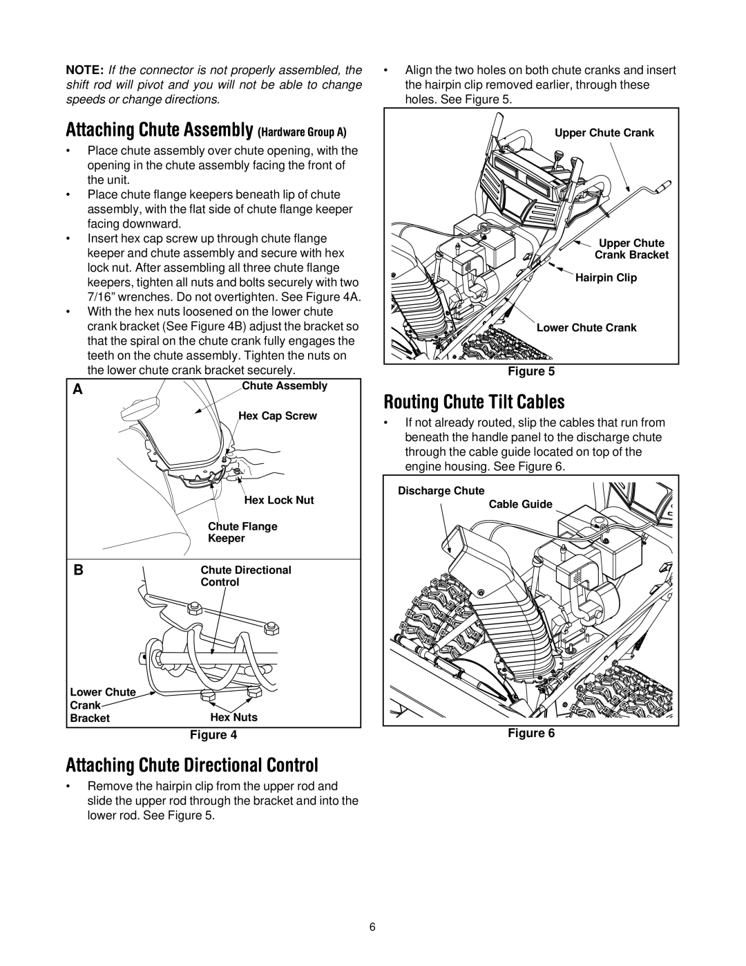
•Place chute assembly over chute opening, with the opening in the chute assembly facing the front of the unit.
•Place chute flange keepers beneath lip of chute assembly, with the flat side of chute flange keeper facing downward.
•Insert hex cap screw up through chute flange keeper and chute assembly and secure with hex lock nut. After assembling all three chute flange keepers, tighten all nuts and bolts securely with two 7/16” wrenches. Do not overtighten. See Figure 4A.
•With the hex nuts loosened on the lower chute crank bracket (See Figure 4B) adjust the bracket so that the spiral on the chute crank fully engages the teeth on the chute assembly. Tighten the nuts on the lower chute crank bracket securely.
A | Chute Assembly |
| Hex Cap Screw |
| Hex Lock Nut |
| Chute Flange |
| Keeper |
B | Chute Directional |
| Control |
Lower Chute |
|
Crank | Hex Nuts |
Bracket |
Figure 4
Attaching Chute Directional Control
•Remove the hairpin clip from the upper rod and slide the upper rod through the bracket and into the lower rod. See Figure 5.
•Align the two holes on both chute cranks and insert the hairpin clip removed earlier, through these holes. See Figure 5.
Upper Chute Crank |
Upper Chute |
Crank Bracket |
Hairpin Clip |
Lower Chute Crank |
Figure 5
Routing Chute Tilt Cables
•If not already routed, slip the cables that run from beneath the handle panel to the discharge chute through the cable guide located on top of the engine housing. See Figure 6.
Discharge Chute |
Cable Guide |
Figure 6
6