Shift Lever
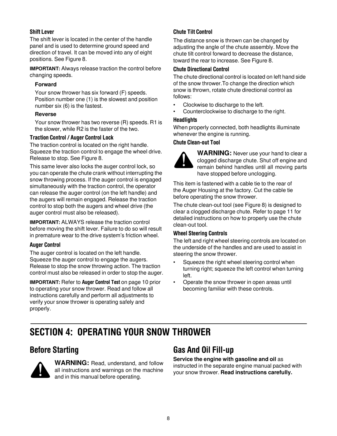
The shift lever is located in the center of the handle panel and is used to determine ground speed and direction of travel. It can be moved into any of eight positions. See Figure 8.
IMPORTANT: Always release traction the control before changing speeds.
Forward
Your snow thrower has six forward (F) speeds. Position number one (1) is the slowest and position number six (6) is the fastest.
Reverse
Chute Tilt Control
The distance snow is thrown can be changed by adjusting the angle of the chute assembly. Move the chute tilt control forward to decrease the distance, toward the rear to increase. See Figure 8.
Chute Directional Control
The chute directional control is located on left hand side of the snow thrower.To change the direction which snow is thrown, rotate chute directional control as follows:
•Clockwise to discharge to the left.
•Counterclockwise to discharge to the right.
Your snow thrower has two reverse (R) speeds. R1 is the slower, while R2 is the faster of the two.
Traction Control / Auger Control Lock
The traction control is located on the right handle. Squeeze the traction control to engage the wheel drive. Release to stop. See Figure 8.
This same lever also locks the auger control lock, so you can operate the chute crank without interrupting the snow throwing process. If the auger control is engaged simultaneously with the traction control, the operator can release the auger control (on the left handle) and the augers will remain engaged. Release the traction control to stop both the augers and wheel drive (the auger control must also be released).
IMPORTANT: ALWAYS release the traction control before moving the shift lever. Failure to do so will result in premature wear to the drive system’s friction wheel.
Auger Control
The auger control is located on the left handle. Squeeze the auger control to engage the augers. Release to stop the snow throwing action. The traction control must also be released in order to stop the auger.
IMPORTANT: Refer to Auger Control Test on page 10 prior to operating your snow thrower. Read and follow all instructions carefully and perform all adjustments to verify your snow thrower is operating safely and properly.
Headlights
When properly connected, both headlights illuminate whenever the engine is running.
Chute Clean-out Tool
WARNING: Never use your hand to clear a clogged discharge chute. Shut off engine and remain behind handles until all moving parts have stopped before unclogging.
This item is fastened with a cable tie to the rear of the Auger Housing at the factory. Cut the cable tie before operating the snow thrower.
The chute
Wheel Steering Controls
The left and right wheel steering controls are located on the underside of the handles and are used to assist in steering the snow thrower.
•Squeeze the right wheel steering control when turning right; squeeze the left control when turning left.
•Operate the snow thrower in open areas until becoming familiar with these controls.
SECTION 4: OPERATING YOUR SNOW THROWER
Before Starting
WARNING: Read, understand, and follow all instructions and warnings on the machine and in this manual before operating.
Gas And Oil Fill-up
Service the engine with gasoline and oil as instructed in the separate engine manual packed with your snow thrower. Read instructions carefully.
8