
13074-GTX 18, 13101 - GTX 16, 13101-GTX 16 specifications
Troy-Bilt has long been a trusted name in outdoor power equipment, and models like the Troy-Bilt 13101-GTX 16, 13101-GTX 16, and 13074-GTX 18 are a testament to the brand’s commitment to quality and innovation. These tillers are designed to make gardening and landscaping tasks efficient and enjoyable, featuring an array of advanced technologies and characteristics that cater to both novice and seasoned gardeners.The Troy-Bilt 13101-GTX 16 is engineered for easy operation and maneuverability. Its lightweight design allows users to navigate around gardens effortlessly. Equipped with a robust 16-inch tilling width, it is perfect for small to medium gardening tasks, providing ample coverage without overwhelming the user. The adjustable tilling depth control system ensures that users can achieve the desired soil conditions for various planting needs.
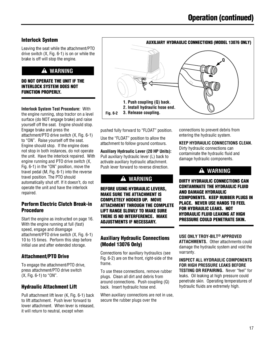
In terms of power, the 13101-GTX 16 is powered by a reliable engine that delivers consistent performance, even in tougher soil conditions. This model also features a gear-driven transmission that allows for smooth operation and better power transfer, ensuring efficient tilling with minimal effort.
The Troy-Bilt 13074-GTX 18 elevates the features found in its 16-inch counterpart, offering a wider 18-inch tilling width. This model is particularly advantageous for larger gardens or plots, allowing users to cover more ground in less time. Moreover, it boasts a heavy-duty build with forged tines that can penetrate even the hardest soil, making it a resilient option for more extensive projects.
Both models incorporate Troy-Bilt’s patented just-a-twist adjustment feature, enabling users to easily switch between forward and reverse tilling directions. This functionality enhances control and versatility, making it easier to navigate around obstacles and till tight spaces.
Another notable feature across these models is the Ergo Handles, designed for comfort and reduced fatigue during extended usage. The cushioned grips provide a secure hold, minimizing vibrations and enhancing user experience.
In summary, the Troy-Bilt 13101-GTX 16, 13101-GTX 16, and 13074-GTX 18 combine user-friendly designs with powerful performance, making them excellent choices for anyone looking to cultivate their green thumb. Whether you are preparing a small flower bed or tilling a larger vegetable garden, these tillers promise reliability, power, and ease, solidifying Troy-Bilt’s reputation as a leading manufacturer in outdoor equipment.