Troy-Bilt 52066, 52070 Inspecting and Replacing the Drive Belt, Belt Inspection, Belt Replacement

Models: 52066 52070

1 28
Download 28 pages 16.71 Kb
Page 14
Image 14

14Section 5: Maintenance

WARNING

Before inspecting, cleaning or servicing the machine, shut off engine, wait for all moving parts to come to a complete stop, disconnect spark plug wire and move wire away from spark plug. Remove ignition key on electric start models.

Failure to follow these instructions can result in serious personal injury or property damage.

INSPECTING AND REPLACING THE DRIVE BELT

The drive belt can be inspected or replaced from beneath the machine deck. Note that the belt should not require inspection for many hours of operation.

Belt Inspection

Stop the engine and let all moving parts stop. Disconnect the spark plug wire and move it away from the spark plug. Re- move the ignition key on electric start models.

1.For convenience, we recommend that you place the unit on a raised platform for easier access to the underside of the deck.

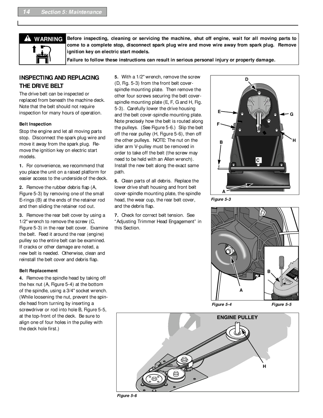
2.Remove the rubber debris flap (A, Figure 5-3) by removing one of the small E-rings (B) at the ends of the retainer rod and then sliding the retainer rod out.

3.Remove the rear belt cover by using a 1/2" wrench to remove the screw (C, Figure 5-3) in the rear belt cover. Examine the belt. Feed it around the rear (engine) pulley so the entire belt can be examined. If cracks or other damage are noted, a new belt is needed. Otherwise, clean and reinstall the belt cover and debris flap.

Belt Replacement

4.Remove the spindle head by taking off the hex nut (A, Figure 5-4) at the bottom of the spindle, using a 3/4" socket wrench. (While loosening the nut, prevent the spin- dle head from turning by inserting a screwdriver or rod into hole B, Figure 5-5, at the top-front of the deck. Be sure to align one of four holes in the pulley with the deck hole first.)

5.With a 1/2" wrench, remove the screw (D, Fig. 5-3) from the front belt cover- spindle mounting plate. Then remove the other four screws securing the belt cover- spindle mounting plate (E, F, G and H, Fig. 5-3). Carefully lower the drive housing and the belt cover-spindle mounting plate. Note precisely how the belt is routed along the pulleys. (See Figure 5-6.) Slip the belt off the rear pulley (H, Figure 5-6), then off the other pulleys. NOTE: The nut on the idler arm V-pulley must be removed in order to take off the belt (the screw may need to be held with an Allen wrench). Install the new belt along the exact same path.

6.Clean parts of all debris. Replace the lower drive shaft housing and front belt cover-spindle mounting plate, the spindle head, the wear cup, the rear belt cover, and the debris flap.

7.Check for correct belt tension. See

“Adjusting Trimmer Head Engagement” in this Section.


D

E

G


F


B

H


C

A


Figure 5-3


B


THROWN

OBJECT H


ROTATING

CUTTING


HEAD


KEEP

HANDS and


DANGERFEET


AWAY


A


Figure 5-4

Figure 5-5


H

Figure 5-6

Page 14
Image 14
Troy-Bilt 52066, 52070 owner manual Inspecting and Replacing the Drive Belt, Belt Inspection, Belt Replacement

52066, 52070 specifications

The Troy-Bilt 52070 and 52066 are powerful tillers designed for home gardening enthusiasts and professionals alike, offering remarkable performance and ease of use. Troy-Bilt, a well-known brand in gardening equipment, has incorporated advanced features and technologies in these models to enhance tilling efficiency and ensure user comfort.

One of the standout features of the Troy-Bilt 52070 and 52066 tillers is their robust engine options. Both models come equipped with a reliable 160cc OHV engine, providing ample power to tackle tough soil types and overgrown garden beds. This engine delivers consistent performance, ensuring that users can complete their tilling tasks in a timely fashion.

The tilling width ranges from 16 to 21 inches, allowing for versatile usage depending on the size of the garden or area being worked on. The adjustable tilling depth, reaching up to 7 inches, ensures that users can cultivate the soil to the desired texture, whether for planting or aerating purposes.

Another innovative aspect of these tillers is the patented Bolo tilling blades. These specially designed blades are engineered to break up tough soil effectively, reducing the amount of effort required and increasing the depth of cultivation. The blades are made from durable materials, ensuring longevity and consistent performance even under demanding conditions.

The Troy-Bilt 52070 and 52066 also feature a user-friendly design, making them accessible to gardeners of all skill levels. The adjustable handlebars offer customizable height settings, enhancing comfort during operation. Additionally, both models are equipped with a forward and reverse self-propulsion system, giving users better control and maneuverability in tight spaces and while navigating through obstacles.

Furthermore, these tillers include a check plug feature for easy oil maintenance, ensuring optimal engine performance over time. The removable and adjustable side shields assist with debris management, keeping the work area tidy and safe.

In conclusion, the Troy-Bilt 52070 and 52066 tillers combine powerful performance with user-friendly features, making them ideal for anyone looking to cultivate their garden efficiently. With their durable construction, advanced tilling technology, and thoughtful design, these models represent a reliable investment for both novice and experienced gardeners.