Manuals
/
Troy-Bilt
/
Lawn and Garden
/
Tiller
Troy-Bilt
634K--ProLine
manual
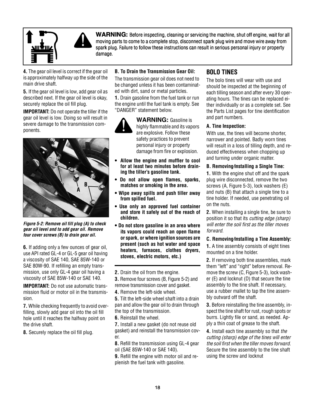
Bolo Tines, B B A, A. Tine Inspection
Models:
634K--ProLine
1
18
32
32
Download
32 pages
57.49 Kb
15
16
17
18
19
20
21
22
Troubleshooting
Safety Alert Symbol
Maintenance
Wheel Drive Pins
Procedure
Handlebar Height Adjustment
Checklist
Engine Cleaning
Replacement Belt Information
Power Composting
Page 18
Image 18
Page 17
Page 19
Page 18
Image 18
Page 17
Page 19
Contents
630C-Tuffy 634A-SuperBroncoTM 634K-ProLine
Operator’s Manual
Rear-tineTiller Models
Troy-BiltLLC, P.O. BOX 361131 CLEVELAND, OHIO
FINDING MODEL NUMBER
TABLE OF CONTENTS
Content
CUSTOMER SUPPORT
Training
SECTION 1 SAFETY
Safety Alert Symbol
Preparation
Maintenance and Storage
c.Use slower engine speeds
Operating Symbols
Decals
TO AVOID SERIOUS INJURY
ASSEMBLY STEPS
SECTION 2 ASSEMBLY
Loose Parts List
Hardware bag contents
STEP 4 INSTALL FORWARD CLUTCH CABLE
T T U
Page
STEP 7 ADD MOTOR OIL
Section 3 Features and Controls
STEP 6 CHECK TRANSMISSION OIL LEVEL
STEP 8 CHECK HARDWARE
WARNING Before
SECTION 3 FEATURES AND CONTROLS
WHEEL DRIVE PINS
INTRODUCTION
To adjust the handlebars
HANDLEBAR HEIGHT ADJUSTMENT
Settings
FORWARD CLUTCH BAIL
BREAK-INOPERATION
Pre-StartChecklist
1.Complete the Pre-StartChecklist on this page
STARTING AND STOPPING
OPERATING THE TILLER
Stopping the Engine and Tiller
Stopping the Tiller and Engine
Let the Tiller Do the Work
TILLING TIPS & TECHNIQUES
Tilling Depths
Avoid Making Footprints
Tilling On Slopes
Power Composting
TILLING TIPS & TECHNIQUES CON’T
WARNING Do not
Clearing the Tines
LOADING AND UNLOADING THE TILLER
Terrace Gardening continued
MAINTENANCE SCHEDULE
SECTION 5 MAINTENANCE
TRANSMISSION GEAR OIL SERVICE
PROCEDURE
BOLO TINES
B. Removing⁄Installing a Single Tine
C. Removing⁄Installing a Tine Assembly
B B A
FORWARD DRIVE BELT TENSION
CHECKING AND ADJUSTING
Replacement Belt Information
To Check Forward Belt Tension
AIR CLEANER SERVICE
FORWARD CLUTCH BAIL ADJUSTMENT
ENGINE CLEANING
ENGINE OIL SERVICE
THROTTLE LEVER ADJUSTMENT
SPARK PLUG SERVICE
SPARK ARRESTER SCREEN SERVICE
CARBURETOR/GOVERNOR CONTROL ADJUSTMENTS
POSSIBLE CAUSE
TROUBLESHOOTING
PROBLEM
CORRECTION
SECTION 6 MODELS 630C, 634A & 634K PARTS LIST
DESCRIPTION
MODELS 630C, 634A & 634K
MODELS 630C, 634A & 634K
DESCRIPTION
DESCRIPTION
MODELS 630C, 634A & 634K
FRONT
MODELS 630C, 634A & 634K
TINE SHAFT
RIGHT-HANDTINE
WHEEL SHAFT
15 28
MODELS 630C, 634A & 634K
TROY-BILTTILLER LIFETIME LIMITED WARRANTY
Top
Page
Image
Contents