Section 2: Assembly
BB
![]() V
V
F
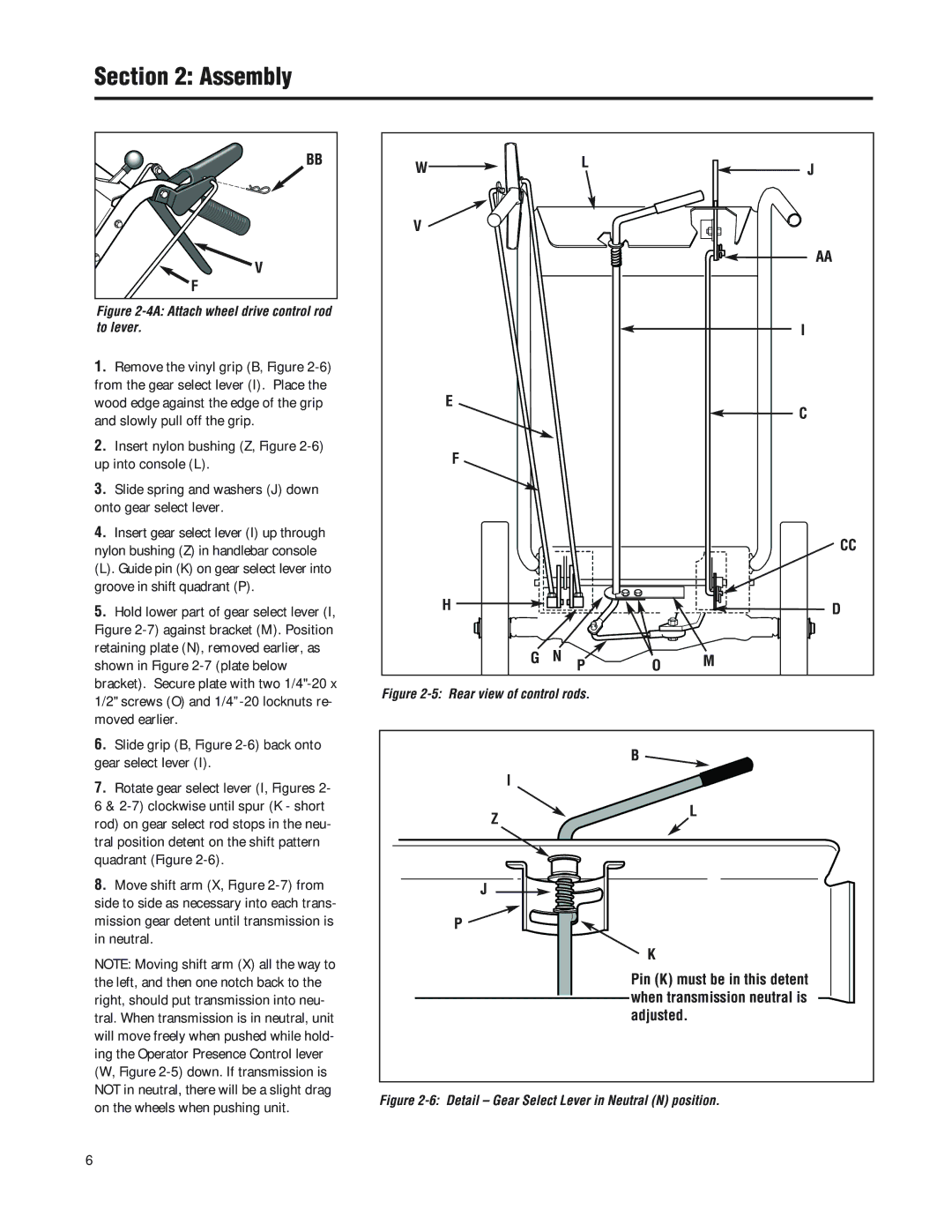
Figure 2-4A: Attach wheel drive control rod to lever.
1.Remove the vinyl grip (B, Figure
2.Insert nylon bushing (Z, Figure
3.Slide spring and washers (J) down onto gear select lever.
4.Insert gear select lever (I) up through nylon bushing (Z) in handlebar console
(L). Guide pin (K) on gear select lever into groove in shift quadrant (P).
5.Hold lower part of gear select lever (I, Figure
6.Slide grip (B, Figure
7.Rotate gear select lever (I, Figures 2-
6&
8.Move shift arm (X, Figure
NOTE: Moving shift arm (X) all the way to the left, and then one notch back to the right, should put transmission into neu- tral. When transmission is in neutral, unit will move freely when pushed while hold- ing the Operator Presence Control lever (W, Figure
W |
| L |
| J |
|
|
| ||
V |
|
|
|
|
|
|
|
| AA |
|
|
|
| I |
E |
|
|
| C |
|
|
|
| |
F |
|
|
|
|
|
|
|
| CC |
H |
|
|
| D |
G | N | P | O | M |
|
Figure 2-5: Rear view of control rods.
| B |
| I |
Z | L |
|
J
P ![]()
K
Pin (K) must be in this detent when transmission neutral is adjusted.
Figure 2-6: Detail – Gear Select Lever in Neutral (N) position.
6