Section 5: Maintenance
WARNING
Before inspecting, cleaning or servicing the machine, shut off engine, wait for moving parts to stop, disconnect spark plug wire and move wire away from spark plug. Remove ignition key (electric start models).
Failure to follow these instructions can result in serious personal injury or property damage.
BLADE BRAKE REPLACEMENT
Follow this procedure to install a new blade brake.
To Remove Blade Brake:
1.Stop engine, wait for all parts to stop moving, and disconnect spark plug wire.
2.Remove belt cover as described in “Belt Cover Removal” instructions.
3.Remove hardware (G, Figure
4.Remove old brake (H) from idler arm (I).
![]() Adjust idler in direction
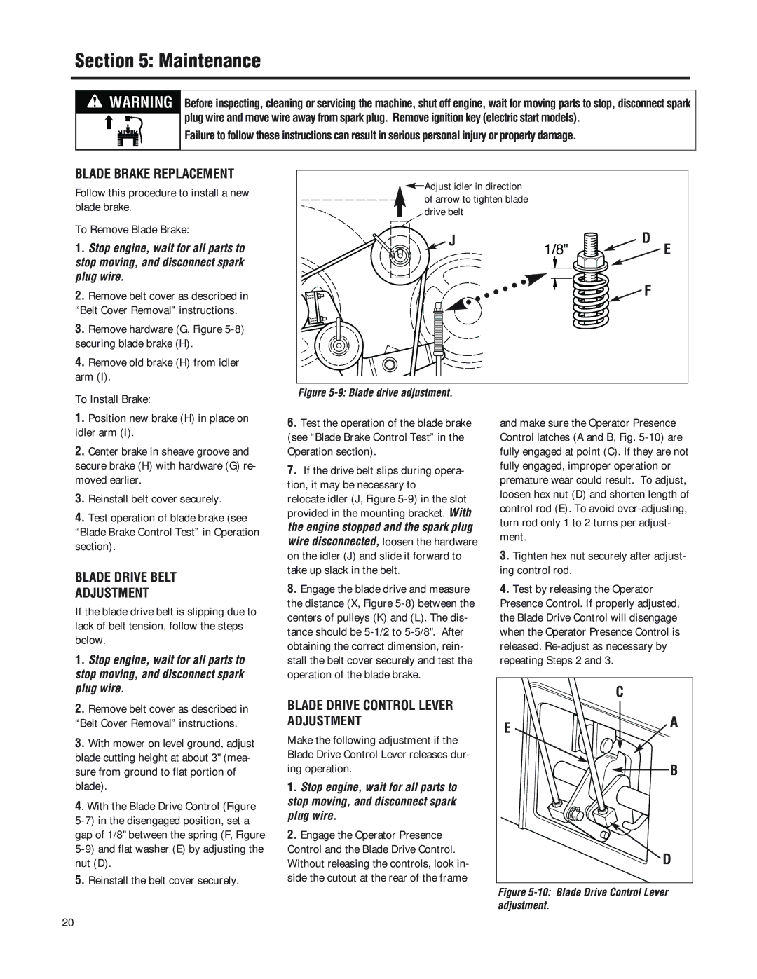
Adjust idler in direction ![]() of arrow to tighten blade drive belt
of arrow to tighten blade drive belt
![]() J
J
1/8" | D |
E |
![]()
![]() F
F
To Install Brake:
1.Position new brake (H) in place on idler arm (I).
2.Center brake in sheave groove and secure brake (H) with hardware (G) re- moved earlier.
3.Reinstall belt cover securely.
4.Test operation of blade brake (see
“Blade Brake Control Test” in Operation section).
BLADE DRIVE BELT
Figure 5-9: Blade drive adjustment.
6.Test the operation of the blade brake (see “Blade Brake Control Test” in the Operation section).
7.If the drive belt slips during opera- tion, it may be necessary to relocate idler (J, Figure
and make sure the Operator Presence Control latches (A and B, Fig.
3.Tighten hex nut securely after adjust- ing control rod.
ADJUSTMENT
If the blade drive belt is slipping due to lack of belt tension, follow the steps below.
1.Stop engine, wait for all parts to stop moving, and disconnect spark plug wire.
2.Remove belt cover as described in “Belt Cover Removal” instructions.
3.With mower on level ground, adjust blade cutting height at about 3" (mea- sure from ground to flat portion of blade).
4. With the Blade Drive Control (Figure
5.Reinstall the belt cover securely.
8.Engage the blade drive and measure the distance (X, Figure
BLADE DRIVE CONTROL LEVER ADJUSTMENT
Make the following adjustment if the Blade Drive Control Lever releases dur- ing operation.
1.Stop engine, wait for all parts to stop moving, and disconnect spark plug wire.
2.Engage the Operator Presence Control and the Blade Drive Control. Without releasing the controls, look in- side the cutout at the rear of the frame
4.Test by releasing the Operator Presence Control. If properly adjusted, the Blade Drive Control will disengage when the Operator Presence Control is released.
| C |
E | A |
| |
| B |
| D |
Figure 5-10: Blade Drive Control Lever adjustment.
20