17.Using pliers, rotate the belt keeper bracket so that it snaps into slot on the idler bracket.
18.Tighten the idler pulley bolt and locknut ½ turn using two 7/16" wrenches. See Figure 22.
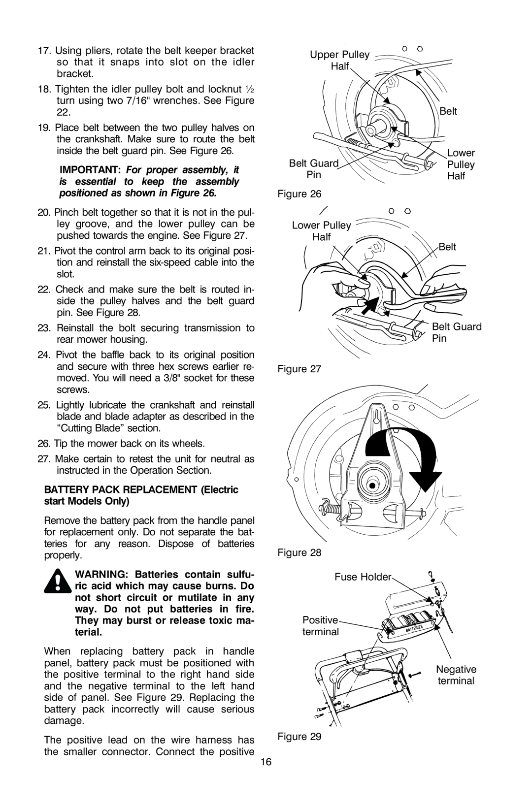
19.Place belt between the two pulley halves on the crankshaft. Make sure to route the belt inside the belt guard pin. See Figure 26.
IMPORTANT: For proper assembly, it is essential to keep the assembly positioned as shown in Figure 26.
20.Pinch belt together so that it is not in the pul- ley groove, and the lower pulley can be pushed towards the engine. See Figure 27.
21.Pivot the control arm back to its original posi- tion and reinstall the
22.Check and make sure the belt is routed in- side the pulley halves and the belt guard pin. See Figure 28.
23.Reinstall the bolt securing transmission to rear mower housing.
24.Pivot the baffle back to its original position and secure with three hex screws earlier re- moved. You will need a 3/8" socket for these screws.
25.Lightly lubricate the crankshaft and reinstall blade and blade adapter as described in the “Cutting Blade” section.
26.Tip the mower back on its wheels.
27.Make certain to retest the unit for neutral as instructed in the Operation Section.
BATTERY PACK REPLACEMENT (Electric
start Models Only)
Upper Pulley
Half
Belt Guard
Pin
Figure 26
Lower Pulley Half ![]()
![]()
Figure 27
Belt
Lower
Pulley
Half
Belt
Belt Guard Pin
Remove the battery pack from the handle panel for replacement only. Do not separate the bat- teries for any reason. Dispose of batteries properly.
WARNING: Batteries contain sulfu- ric acid which may cause burns. Do not short circuit or mutilate in any way. Do not put batteries in fire. They may burst or release toxic ma- terial.
When replacing battery pack in handle panel, battery pack must be positioned with the positive terminal to the right hand side and the negative terminal to the left hand side of panel. See Figure 29. Replacing the battery pack incorrectly will cause serious damage.
The positive lead on the wire harness has the smaller connector. Connect the positive
16
Figure 28
Fuse Holder
Positive terminal
Figure 29
Negative terminal
