
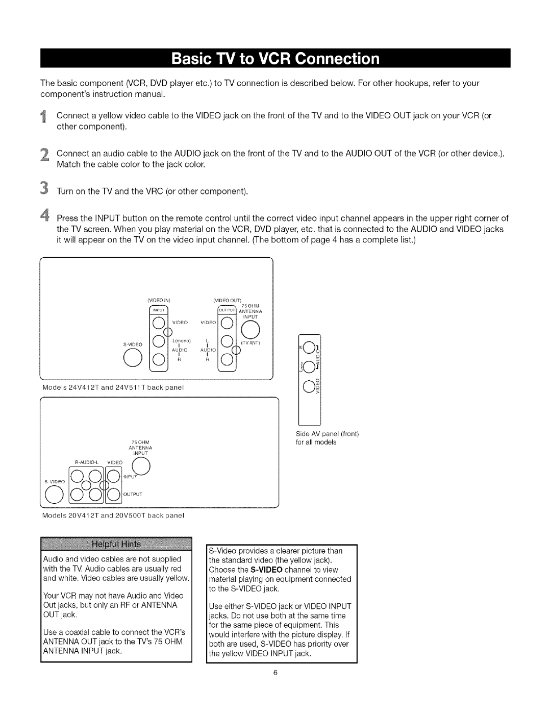
CRT Television specifications
The TTE Technology CRT Television represents a significant era in video display technology, known for its robust image reproduction and reliability. Although it is largely overshadowed by modern flat-screen displays, the CRT (Cathode Ray Tube) television holds a unique place in the hearts of many. TTE Technology has been a notable player in the CRT market, offering televisions that exemplify the classic characteristics of the technology.One of the main features of TTE Technology CRT Televisions is their high-quality picture clarity. These televisions utilize a cathode ray tube, which generates images by directing electron beams onto a phosphorescent screen. This process produces vivid colors and deep blacks, giving a lifelike feel to images. Many users appreciate the rich color saturation and contrast that CRTs can provide, especially in darker scenes.
Another hallmark of TTE CRT Televisions is their durability and long lifespan. Unlike many modern displays, which can suffer from issues like dead pixels or burn-in, CRTs are generally capable of withstanding years of use without significant deterioration in image quality. This longevity makes them a preferred choice for those looking for a reliable viewing option.
TTE Technology CRT Televisions also offer various screen sizes, typically ranging from 14 to 36 inches. This variety allows users to select a size that fits their viewing environment without the need for overwhelming space. The compact design of CRT televisions makes them suitable for smaller rooms or locations where space is limited.
One notable technological characteristic of TTE CRT Televisions is the cathode ray tube's ability to display various resolutions and aspect ratios. While many flat screens have fixed resolutions and aspect ratios, CRTs can adapt to different content formats, accommodating both standard definition and various high-definition signals, although the latter may not exhibit the same level of quality as modern displays.
In addition to their visual characteristics, TTE CRT Televisions are also appreciated for their sound quality. Many models come equipped with built-in speakers that deliver robust sound, creating an immersive experience for viewers.
While they may not feature the smart capabilities of contemporary televisions, TTE Technology CRT Televisions are celebrated for their nostalgic charm, vivid image quality, and lasting durability. For enthusiasts and collectors, these televisions represent a unique connection to a time when viewing experiences were defined by the technology of the cathode ray tube.