MC-125 specifications
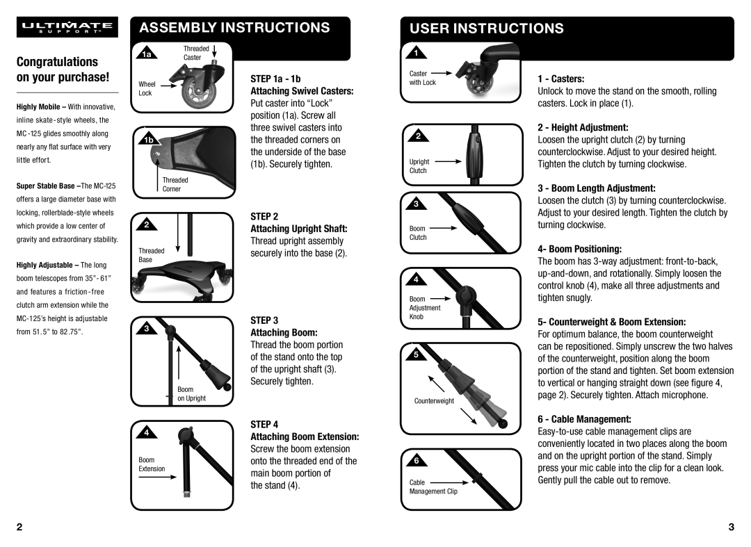
The Ultimate Support Systems MC-125 is a cutting-edge microphone stand designed to meet the demands of musicians, sound engineers, and vocalists alike. With its robust construction and thoughtful design, it offers both functionality and durability that professionals require in various performance contexts.One of the standout features of the MC-125 is its adjustable height, allowing users to customize the stand's height between 36 inches and 63 inches. This versatility makes it suitable for different types of performances and setups, whether on stage, in the studio, or during rehearsals. The easy-to-use height adjustment mechanism ensures that users can quickly set the stand to their preferred height without any hassle.
The MC-125 features a sturdy tripod base, which ensures stability during use. This base design prevents tipping and swaying, allowing performers to focus on their act without the distraction of a wobbling microphone stand. The high-quality materials used in the construction of the stand enhance its strength while keeping it lightweight enough for easy portability.
In terms of technology, the MC-125 incorporates a clever clutch mechanism that locks the adjustable height securely into place. This feature eliminates the concerns associated with accidental height adjustments during performance, reassuring performers that their microphone will remain at the desired height.
The microphone mounting system on the MC-125 is equally impressive. It includes a standard microphone clip, compatible with most microphones on the market. Additionally, the stand’s threaded end is designed to fit a wide range of microphone accessories, enhancing its versatility as a tool for all types of audio applications.
Another significant characteristic of the MC-125 is its durability. Made from high-quality steel and resistant finishes, this stand is built to withstand the rigors of frequent transport and heavy use. It can easily handle the physical demands of touring musicians and busy studios, proving its reliability in various situations.
Overall, the Ultimate Support Systems MC-125 is an exemplary microphone stand that combines innovative design, user-friendly features, and reliable performance. It caters to the needs of professionals seeking a sturdy and adjustable microphone support solution that can keep up with their dynamic lifestyle. Whether on stage or in the studio, the MC-125 stands out as an essential tool for capturing sound effortlessly and effectively.

