3.Fitting the new printhead to the heatsink assembly (Magicard Dealers Only)
CAUTION - The following procedures involve contact with the new printhead, all precautions for handling Electrostatic Sensitive Devices should be followed at all times, including the use of a grounded wrist strap. Furthermore great care must be taken not to touch or damage the printing elements of the printhead.
(1)Ensure that the brass backing plate attached to new printhead has a very thin, evenly spread film of graphite grease over its surface.
(2)Apply a very small amount of Loctite 242 Threadlocker to the hole in the brass backing plate into which the printhead pivot screw will shortly be inserted .
(3)With the heatsink still in position on the bench, slide in the new printhead until the two pivot screw holes are aligned and insert the pivot screw with its washers (thin crinkly washer closest to the head of the screw).
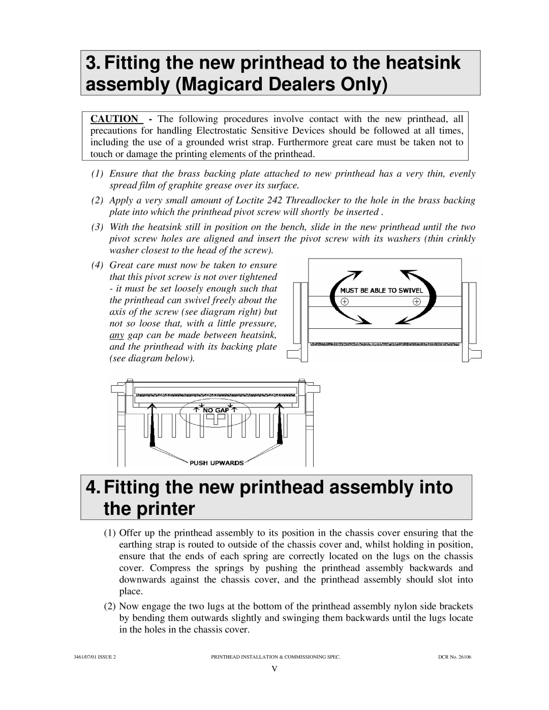
(4)Great care must now be taken to ensure that this pivot screw is not over tightened - it must be set loosely enough such that
the printhead can swivel freely about the axis of the screw (see diagram right) but not so loose that, with a little pressure, any gap can be made between heatsink, and the printhead with its backing plate (see diagram below).
4.Fitting the new printhead assembly into the printer
(1)Offer up the printhead assembly to its position in the chassis cover ensuring that the earthing strap is routed to outside of the chassis cover and, whilst holding in position, ensure that the ends of each spring are correctly located on the lugs on the chassis cover. Compress the springs by pushing the printhead assembly backwards and downwards against the chassis cover, and the printhead assembly should slot into place.
(2)Now engage the two lugs at the bottom of the printhead assembly nylon side brackets by bending them outwards slightly and swinging them backwards until the lugs locate in the holes in the chassis cover.
3461/07/01 ISSUE 2 | PRINTHEAD INSTALLATION & COMMISSIONING SPEC. | DCR No. 26106 |
V