Hardware Description
The Front Panel
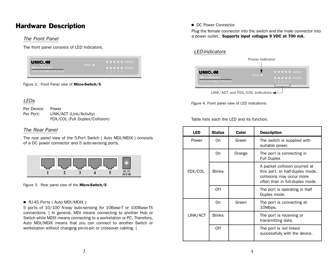
The front panel consists of LED Indicators.
|
| Power |
|
|
|
|
|
|
|
|
|
|
| LINK/ACT |
|
| |||||||||||||
| ||||||||||||||
| ||||||||||||||
|
|
|
|
|
|
|
|
|
|
|
| FDX/COL | ||
|
|
|
|
|
|
|
| |||||||
5 Port | 1 2 3 4 5 |
| ||||||||||||
|
|
|
|
|
|
|
|
|
|
|
|
|
|
|
Figure 2. Front Panel view of Micro-Switch/5
LEDs
Per Device: | Power |
Per Port: | LINK/ACT (Link/Activity) |
| FDX/COL (Full Duplex/Collision) |
The Rear Panel
The rear panel view of the
1 | 2 | 3 | 4 | 5 | DC IN |
| |||||
|
|
|
|
|
|
Figure 3. Rear panel view of the Micro-Switch/5
■
5 ports of 10/100
■DC Power Connector
Plug the female connector into the switch and the male connector into a power outlet. Supports input voltages 9 VDC at 700 mA.
LED-Indicators
|
|
| Power Indicator | ||||||||||||
|
|
| Power |
|
|
|
|
|
|
|
|
|
|
| LINK/ACT |
|
|
|
|
|
|
|
|
|
|
|
|
|
| ||
|
|
|
|
|
|
|
|
|
|
|
|
|
| ||
|
|
| |||||||||||||
| |||||||||||||||
| |||||||||||||||
|
|
|
|
|
|
|
|
|
|
|
| FDX/COL | |||
|
|
|
|
|
|
|
| ||||||||
|
|
|
|
|
|
|
| ||||||||
5 Port | 1 2 3 4 5 |
| |||||||||||||
LINK/ACT and FDX/COL Indicators![]()
![]()
Figure 4. Front panel view of LED indications
Table lists each the LED and its function.
LED | Status | Color | Description |
|
|
|
|
Power | On | Green | The switch is supplied with |
|
|
| suitable power. |
|
|
|
|
| On | Orange | The port is connecting in |
|
|
| Full Duplex |
|
|
|
|
|
|
| A packet collision ocurred at |
FDX/COL | Blinks |
| this port. In |
|
|
| collisions may occur more |
|
|
| often than in |
|
|
|
|
| Off |
| The port is operating in Half |
|
|
| Duplex mode. |
|
|
|
|
| On | Green | The port is connecting at |
|
|
| 10Mbps. |
|
|
|
|
LINK/ACT | Blinks |
| The port is receiving or |
|
|
| transmitting data. |
|
|
|
|
| Off |
| The port is not linked |
|
|
| successfully with the device. |
|
|
|
|
3 | 4 |
