
GRANT specifications
The Uniden GRANT is a notable citizen band (CB) transceiver that has captured the attention of radio enthusiasts and operators alike. Known for its versatility and reliability, this model stands out in the crowded world of CB radios. Ideal for both personal and professional use, the Uniden GRANT offers a plethora of features that cater to various communication needs.One of the main features of the Uniden GRANT is its powerful 40-channel capability. This allows users to access a wide range of frequencies, providing ample options for communication with others in the CB band. The channel selection is straightforward, facilitated by a user-friendly knob that enables quick navigation through the options.
In addition to its extensive channel range, the GRANT includes several advanced technologies that enhance its performance. The radio is equipped with a built-in squelch function, which filters out background noise and ensures a clearer audio experience. This feature is particularly useful in noisy environments, making conversations more intelligible.
Another key characteristic of the Uniden GRANT is its compact and durable design. It is designed for easy mounting in vehicles, with a sleek appearance that blends well with modern interiors. The robust construction ensures it can withstand the rigors of daily use, whether on long-haul trips or during off-road adventures.
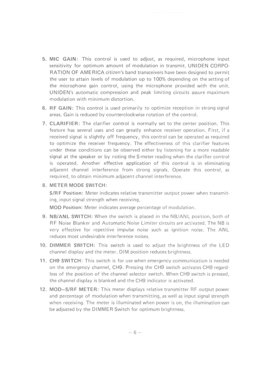
The Uniden GRANT also includes an RF Gain control, allowing users to adjust reception sensitivity based on their surroundings. This flexibility is essential, particularly in areas with varying signal strengths, ensuring optimal communication regardless of location.
Moreover, the radio features a built-in PA system, enabling users to broadcast messages through an external speaker. This feature is particularly beneficial for applications such as directing traffic or communicating with people at a distance without the need for a separate microphone.
In terms of ease of use, the Uniden GRANT offers a bright LCD display that clearly shows the selected channel and other vital information, such as signal strength and battery status. This display is complemented by backlit controls, ensuring visibility in low-light conditions.
In conclusion, the Uniden GRANT is a well-rounded CB transceiver that combines advanced features, robust design, and user-friendly operation. Whether for recreational use or professional applications, its capabilities make it a reliable choice for individuals needing effective communication solutions. With its powerful performance and practical features, the Uniden GRANT continues to be a popular option among radio operators.