3.The front panel can be fully reversed to provide for optimum viewing area, operat- ing for any mounting position.
4.The EXTERNAL speaker jack may be used with an auxiliary speaker in lieu of the
5.All connections are
ACTUAL INSTAllATION
After carefully considering the various factors affecting choice of location, position the radio (with bracket, microphone, power plug, antenna plug and any auxiliary plugs installed) into the selected location to assure there is no interference with surrounding items. Mark the location of the mounting bracket. Remove the bracket from the radio and use it as a template to mark the holes to be drilled for the mount- ing hardware. Drill the holes and mount the bracket with hardware compatible with the material of the mounting surface. Install the power cable (red is +, black is
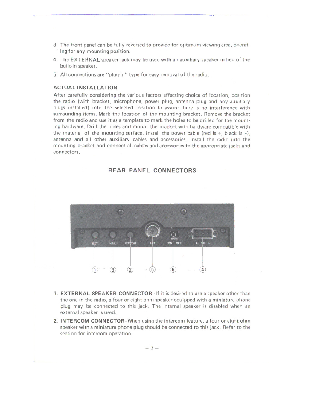
REAR PANEL CONNECTORS
Cl} . CID @ " CID@ | @ |
1.EXTERNAL SPEAKER
2.INTERCOM
