Installation Instructions
INSTALLATION REQUIREMENTS FOR ALL AVTEC TAKU VENTILATION HOODS
CANOPIES
Avtec hoods are provided with adjustable hanging brackets designed to receive 1/2” threaded rod with a 1/2” nut and washer. Supporting rods must be connected to all factory
installed brackets. Recommended hanging height is
ALL AVTEC VENTILATION SYSTEMS MUST BE INSTALLED IN ACCOR- DANCE WITH
1.Check all local codes prior to installation. Special requirements may be necessary depending upon building material construction.
2.Move crated hood to location of installation and very carefully uncrate hood.
3.Raise hood to proper hanging height.
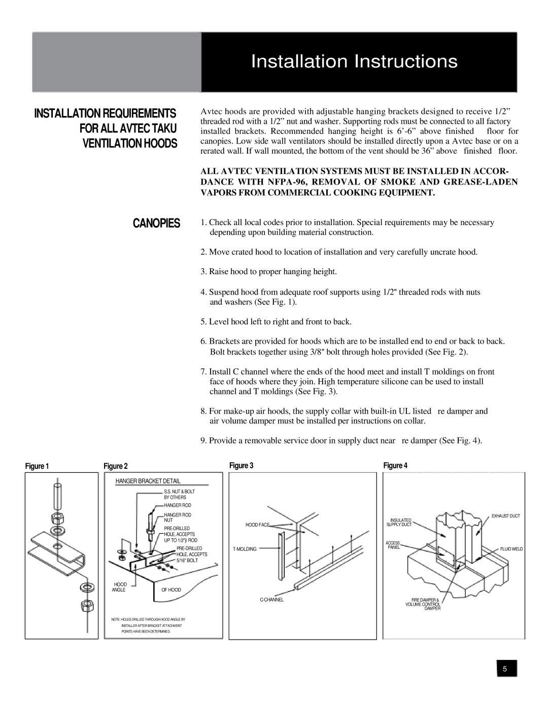
4.Suspend hood from adequate roof supports using 1/2" threaded rods with nuts and washers (See Fig. 1).
5.Level hood left to right and front to back.
6.Brackets are provided for hoods which are to be installed end to end or back to back. Bolt brackets together using 3/8" bolt through holes provided (See Fig. 2).
7.Install C channel where the ends of the hood meet and install T moldings on front face of hoods where they join. High temperature silicone can be used to install channel and T moldings (See Fig. 3).
8. | For |
| air volume damper must be installed per instructions on collar. |
9. | Provide a removable service door in supply duct near re damper (See Fig. 4). |
Figure 1 | Figure 2 |
HANGER BRACKET DETAIL
S.S. NUT & BOLT
BY OTHERS
HANGER ROD
HANGER ROD
NUT
HOLE, ACCEPTS
UP TO 1/2"ÿ ROD
HOOD |
|
ANGLE | OF HOOD |
NOTE: HOLES DRILLED THROUGH HOOD ANGLE BY
INSTALLER AFTER BRACKET ATTACHMENT
POINTS HAVE BEEN DETERMINED.
Figure 3
HOOD FACE
Figure 4
EXHAUST DUCT
INSULATED
SUPPLY DUCT |
|
ACCESS |
|
PANEL | FLUID WELD |
|
FIRE DAMPER &
VOLUME CONTROL
DAMPER
5