BLOWER ASSEMBLY for Model 2007B
KEY | DESCRIPTION | PART NO. | QTY. |
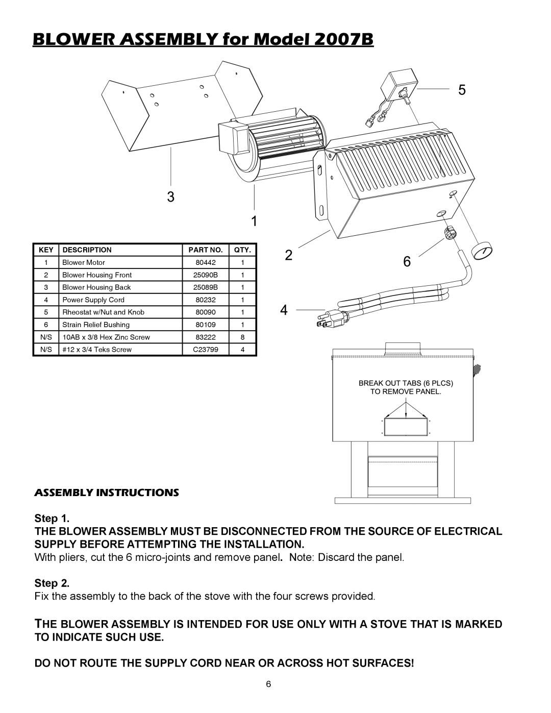
1 | Blower Motor | 80442 | 1 |
2 | Blower Housing Front | 25090B | 1 |
3 | Blower Housing Back | 25089B | 1 |
|
|
|
|
4 | Power Supply Cord | 80232 | 1 |
5 | Rheostat w/Nut and Knob | 80090 | 1 |
|
|
|
|
6 | Strain Relief Bushing | 80109 | 1 |
N/S | 10AB x 3/8 Hex Zinc Screw | 83222 | 8 |
|
|
|
|
N/S | #12 x 3/4 Teks Screw | C23799 | 4 |
ASSEMBLY INSTRUCTIONS
Step 1.
THE BLOWER ASSEMBLY MUST BE DISCONNECTED FROM THE SOURCE OF ELECTRICAL SUPPLY BEFORE ATTEMPTING THE INSTALLATION.
With pliers, cut the 6
Step 2.
Fix the assembly to the back of the stove with the four screws provided.
THE BLOWER ASSEMBLY IS INTENDED FOR USE ONLY WITH A STOVE THAT IS MARKED TO INDICATE SUCH USE.
DO NOT ROUTE THE SUPPLY CORD NEAR OR ACROSS HOT SURFACES!
6