Interconnected CO alarms will only respond if a CO alarm / event initiates the alarm. All other alarms remain silent.
Interconnected smoke alarms, heat alarms and relay modules will only respond if a smoke alarm / event or heat alarm / event initiates the alarm. All CO alarms remain silent.
NOTE: Relay
NOTE: Units without battery backup will not respond during an AC power failure.
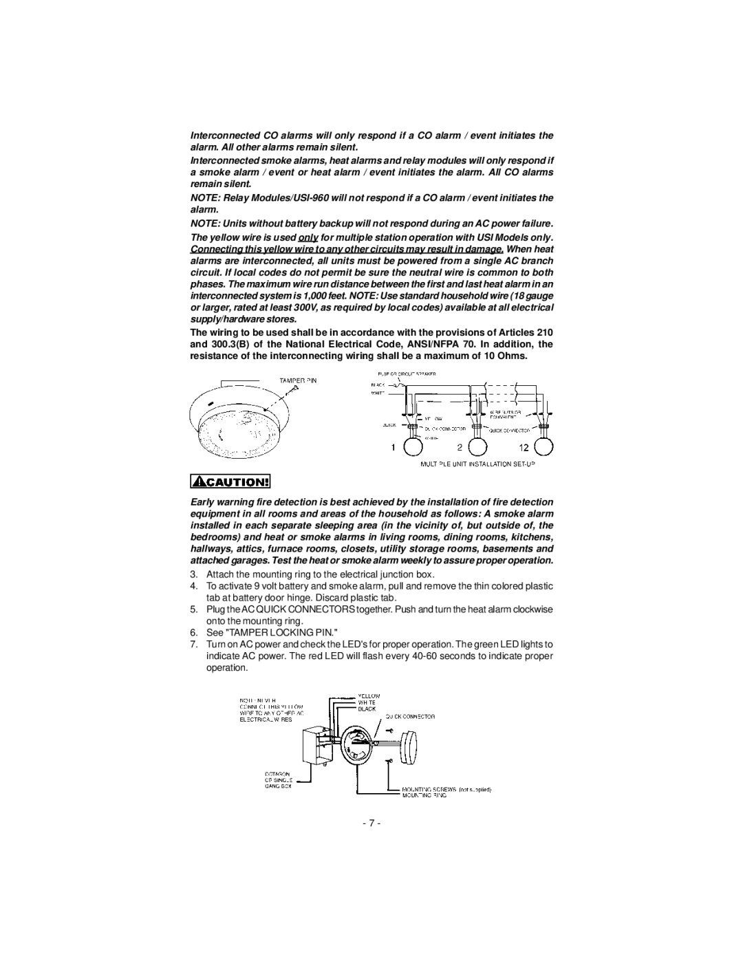
The yellow wire is used only for multiple station operation with USI Models only. Connecting this yellow wire to any other circuits may result in damage. When heat alarms are interconnected, all units must be powered from a single AC branch circuit. If local codes do not permit be sure the neutral wire is common to both phases. The maximum wire run distance between the first and last heat alarm in an interconnected system is 1,000 feet. NOTE: Use standard household wire (18 gauge or larger, rated at least 300V, as required by local codes) available at all electrical supply/hardware stores.
The wiring to be used shall be in accordance with the provisions of Articles 210 and 300.3(B) of the National Electrical Code, ANSI/NFPA 70. In addition, the resistance of the interconnecting wiring shall be a maximum of 10 Ohms.
Early warning fire detection is best achieved by the installation of fire detection equipment in all rooms and areas of the household as follows: A smoke alarm installed in each separate sleeping area (in the vicinity of, but outside of, the bedrooms) and heat or smoke alarms in living rooms, dining rooms, kitchens, hallways, attics, furnace rooms, closets, utility storage rooms, basements and attached garages. Test the heat or smoke alarm weekly to assure proper operation.
3.Attach the mounting ring to the electrical junction box.
4.To activate 9 volt battery and smoke alarm, pull and remove the thin colored plastic tab at battery door hinge. Discard plastic tab.
5.Plug the AC QUICK CONNECTORS together. Push and turn the heat alarm clockwise onto the mounting ring.
6.See "TAMPER LOCKING PIN."
7.Turn on AC power and check the LED's for proper operation. The green LED lights to indicate AC power. The red LED will flash every
- 7 -