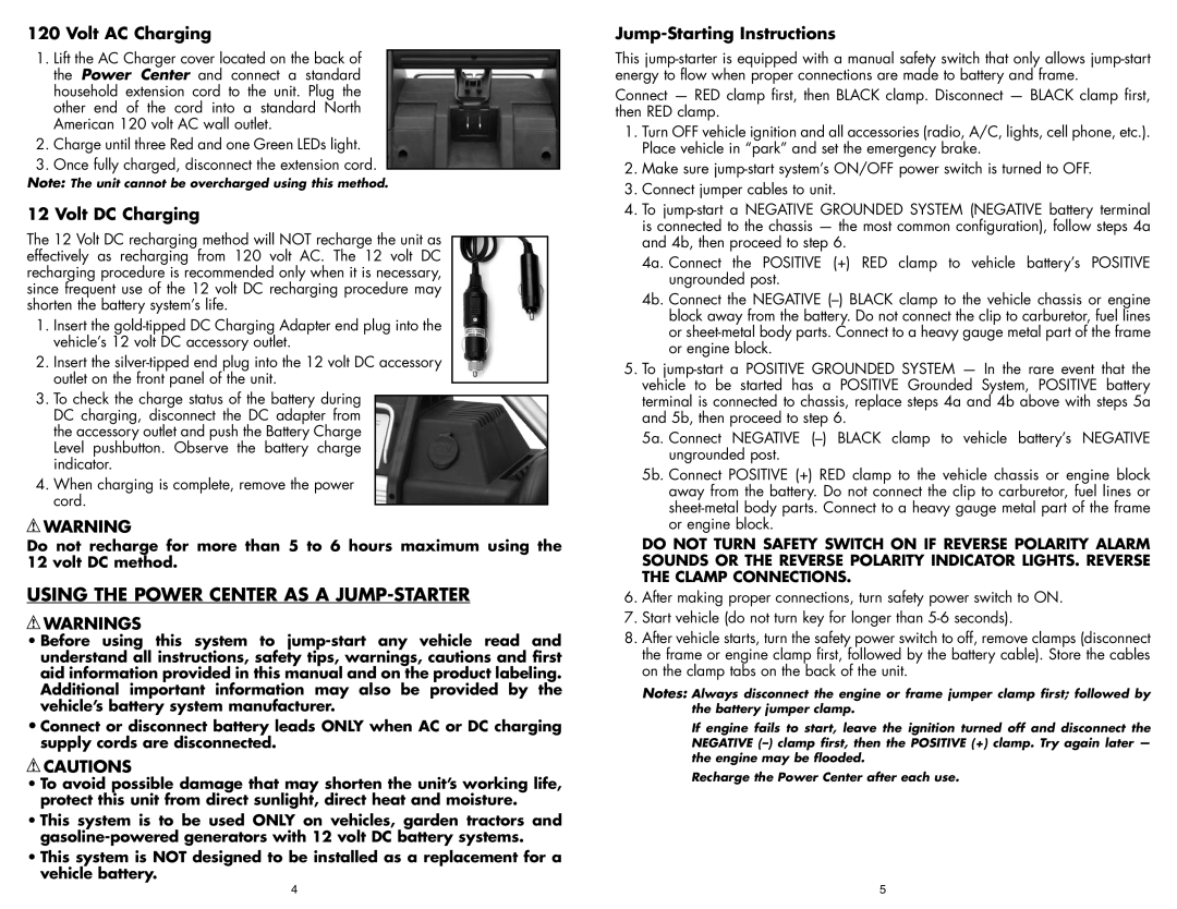
120 Volt AC Charging

1.Lift the AC Charger cover located on the back of the Power Center and connect a standard household extension cord to the unit. Plug the other end of the cord into a standard North American 120 volt AC wall outlet.

2.Charge until three Red and one Green LEDs light.

3.Once fully charged, disconnect the extension cord.

Note: The unit cannot be overcharged using this method.

12 Volt DC Charging

The 12 Volt DC recharging method will NOT recharge the unit as effectively as recharging from 120 volt AC. The 12 volt DC recharging procedure is recommended only when it is necessary, since frequent use of the 12 volt DC recharging procedure may shorten the battery system’s life.

1.Insert the gold-tipped DC Charging Adapter end plug into the vehicle’s 12 volt DC accessory outlet.

2.Insert the silver-tipped end plug into the 12 volt DC accessory outlet on the front panel of the unit.

3.To check the charge status of the battery during DC charging, disconnect the DC adapter from the accessory outlet and push the Battery Charge Level pushbutton. Observe the battery charge indicator.

4.When charging is complete, remove the power cord.

WARNING

Do not recharge for more than 5 to 6 hours maximum using the 12 volt DC method.

USING THE POWER CENTER AS A JUMP-STARTER

WARNINGS

Before using this system to jump-start any vehicle read and understand all instructions, safety tips, warnings, cautions and first aid information provided in this manual and on the product labeling. Additional important information may also be provided by the vehicle’s battery system manufacturer.

Connect or disconnect battery leads ONLY when AC or DC charging supply cords are disconnected.

CAUTIONS

To avoid possible damage that may shorten the unit’s working life, protect this unit from direct sunlight, direct heat and moisture.

This system is to be used ONLY on vehicles, garden tractors and gasoline-powered generators with 12 volt DC battery systems.

This system is NOT designed to be installed as a replacement for a vehicle battery.

Jump-Starting Instructions

This jump-starter is equipped with a manual safety switch that only allows jump-start energy to flow when proper connections are made to battery and frame.

Connect — RED clamp first, then BLACK clamp. Disconnect — BLACK clamp first, then RED clamp.

1.Turn OFF vehicle ignition and all accessories (radio, A/C, lights, cell phone, etc.). Place vehicle in “park” and set the emergency brake.

2.Make sure jump-start system’s ON/OFF power switch is turned to OFF.

3.Connect jumper cables to unit.

4.To jump-start a NEGATIVE GROUNDED SYSTEM (NEGATIVE battery terminal is connected to the chassis — the most common configuration), follow steps 4a and 4b, then proceed to step 6.

4a. Connect the POSITIVE (+) RED clamp to vehicle battery’s POSITIVE ungrounded post.

4b. Connect the NEGATIVE (–) BLACK clamp to the vehicle chassis or engine block away from the battery. Do not connect the clip to carburetor, fuel lines or sheet-metal body parts. Connect to a heavy gauge metal part of the frame or engine block.

5.To jump-start a POSITIVE GROUNDED SYSTEM — In the rare event that the vehicle to be started has a POSITIVE Grounded System, POSITIVE battery terminal is connected to chassis, replace steps 4a and 4b above with steps 5a and 5b, then proceed to step 6.

5a. Connect NEGATIVE (–) BLACK clamp to vehicle battery’s NEGATIVE ungrounded post.

5b. Connect POSITIVE (+) RED clamp to the vehicle chassis or engine block away from the battery. Do not connect the clip to carburetor, fuel lines or sheet-metal body parts. Connect to a heavy gauge metal part of the frame or engine block.

DO NOT TURN SAFETY SWITCH ON IF REVERSE POLARITY ALARM SOUNDS OR THE REVERSE POLARITY INDICATOR LIGHTS. REVERSE THE CLAMP CONNECTIONS.

6.After making proper connections, turn safety power switch to ON.

7.Start vehicle (do not turn key for longer than 5-6 seconds).

8.After vehicle starts, turn the safety power switch to off, remove clamps (disconnect the frame or engine clamp first, followed by the battery cable). Store the cables on the clamp tabs on the back of the unit.

Notes: Always disconnect the engine or frame jumper clamp first; followed by the battery jumper clamp.

If engine fails to start, leave the ignition turned off and disconnect the NEGATIVE (–) clamp first, then the POSITIVE (+) clamp. Try again later — the engine may be flooded.

Recharge the Power Center after each use.

4

5

Page 5
Image 5
Vector BD051605 Using the Power Center AS a JUMP-STARTER, Volt AC Charging, Volt DC Charging, Jump-Starting Instructions

BD051605, VEC1028POB specifications

Vector BD051605 and VEC1028POB are two innovative products in the realm of advanced vehicle technology, specifically designed for enhancing mobility and engineering applications. These devices embody exceptional design and functionality, catering to various modern vehicular needs.

The Vector BD051605 is a high-performance controller that is primarily aimed at managing electric motor operations in electric and hybrid electric vehicles. Its standout features include a versatile communication interface, enabling integration with multiple sensors and control units. This flexibility allows it to be employed in a variety of vehicle platforms. The BD051605 supports advanced modulation techniques which contribute to improved efficiency and performance of electric drive systems. With its robust thermal management design, this controller ensures reliable operation even under demanding conditions, making it a preferred choice for manufacturers seeking optimum reliability.

On the other hand, the VEC1028POB is a compact yet powerful power distribution unit known for its capability to manage multiple electrical loads seamlessly. This unit incorporates state-of-the-art technologies that enhance safety and efficiency across various electrical systems. A notable feature is its integrated fault detection mechanism, which provides real-time diagnostics and predictive maintenance alerts. This characteristic not only enhances reliability but also minimizes downtime, which is critical in commercial applications.

Both devices leverage cutting-edge technologies such as CAN bus communications, which facilitate high-speed data transfer between components, ensuring that information is readily available for decision-making processes. The integration of advanced algorithms within both the BD051605 and VEC1028POB allows for dynamic adjustments according to vehicle performance parameters, optimizing energy usage and improving overall vehicle efficiency.

In conclusion, Vector BD051605 and VEC1028POB combinedly represent a significant leap forward in vehicle technology. Their superior features, including enhanced communication, reliability, and real-time diagnostics, position them as essential components for contemporary electric and hybrid vehicles. As the automotive industry continues to evolve towards greater electrification and automation, these technologies provide practical solutions that support this transition while ensuring safety and performance efficiency. Their implementation not only drives advancements in vehicle engineering but also aligns with the growing demand for sustainable mobility solutions.