810, 1012XII specifications
Velodyne Acoustics, a renowned name in the world of audio technology, has consistently delivered innovative products that enhance the listening experience. Among their impressive lineup is the Velodyne Acoustics 1012XII,810 subwoofer, a testament to the company's commitment to pushing audio boundaries.The Velodyne 1012XII,810 features advanced technologies designed to provide an exceptional low-frequency response, making it a vital component for both home theaters and high-fidelity sound systems. One of its key features is the integration of a powerful 1000-watt RMS amplifier that ensures deep and impactful sounds, allowing users to feel every beat and nuance in their music or cinematic experience.
This subwoofer is equipped with a 12-inch front-firing driver, which delivers robust bass frequencies with minimal distortion. The driver is engineered for precision and efficiency, enabling the subwoofer to reproduce sound with incredible clarity even at high volumes. The enclosure is designed with a ported bass reflex system, enhancing the overall performance while reducing air turbulence and potential noise.
The 1012XII,810 incorporates Velodyne's proprietary Digital Signal Processing (DSP) technology, which plays a crucial role in optimizing the sound output. The DSP ensures that the audio is dynamically adjusted based on the content being played, resulting in a more immersive experience. Users can easily customize the sound settings with the intuitive user interface, allowing for adjustments that meet individual preferences.
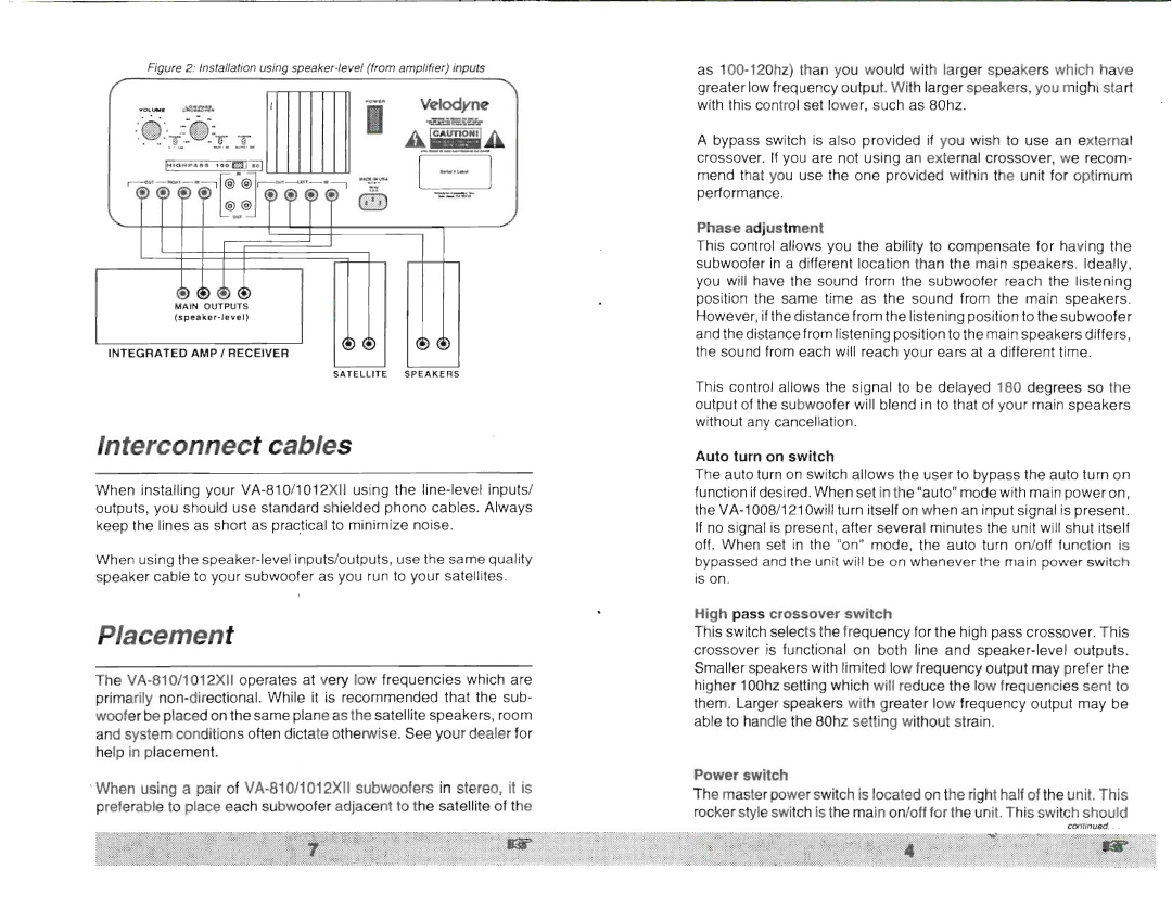
Another significant aspect of the Velodyne 1012XII,810 is its advanced connectivity options. It features both line-level and LFE inputs, making it compatible with various audio setups and receivers. The inclusion of remote control functionality adds to its convenience, allowing users to manage settings and power from the comfort of their seats.
In terms of build quality, the Velodyne Acoustics 1012XII,810 boasts a robust construction that minimizes resonance and ensures durability. Its sleek design complements any decor, while the attention to detail in its finish accentuates its premium quality.
Overall, the Velodyne Acoustics 1012XII,810 subwoofer stands out as an excellent choice for audiophiles and home theater enthusiasts alike. With its impressive power, precision, and customizable sound features, it promises to elevate the audio experience to new heights, ensuring that every listening session is as thrilling as the last. Whether immersing in the rumble of a movie or the thumping bass of music, this subwoofer delivers in every aspect.

