Audio/Video Subwoofer System specifications
Velodyne Acoustics has long been recognized as a leader in the field of high-performance audio solutions, and their Audio/Video Subwoofer System exemplifies the brand's commitment to delivering an immersive auditory experience. Known for its advanced engineering and attention to detail, this subwoofer system combines innovative technologies and characteristics that cater to both audiophiles and home theater enthusiasts.One of the standout features of the Velodyne subwoofer is its use of proprietary Smart Drive technology. This system allows for precise monitoring and adjustment of the subwoofer's performance in real time, ensuring optimal bass response across varying volume levels. The result is a deep, clear, and distortion-free sound that enhances the overall audio experience whether you're enjoying music or watching movies.
The subwoofer's robust construction ensures durability while minimizing unwanted resonance. With a reinforced MDF cabinet and a front-firing design, it delivers powerful low frequencies without compromising clarity. The enclosure is designed to reduce vibration and improve sound fidelity, making it an excellent addition to any audio setup.
Another key characteristic of Velodyne's subwoofer systems is the integration of advanced digital signal processing (DSP). This technology optimizes the audio output by analyzing the incoming signal and adjusting it to provide the best possible bass response. Users can expect precision tuning that aligns with their specific room acoustics, leading to a richer and more responsive low-end sound.
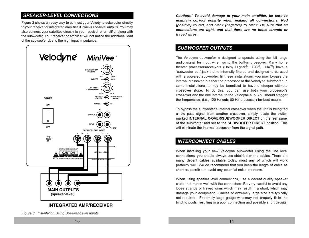
Additionally, Velodyne offers various connectivity options, allowing for seamless integration with an array of audio/video components. With multiple RCA inputs and outputs, as well as wireless capabilities in certain models, users can easily connect their AV receivers, televisions, and other devices. This versatility ensures that the subwoofer can fit into any entertainment system without hassle.
The Velodyne Acoustics Audio/Video Subwoofer System is designed with user-friendly controls and intuitive interfaces. Features like adjustable crossover settings and phase adjustment provide users with the ability to fine-tune their listening experience. For those who appreciate convenience, remote control options are available to control the subwoofer from a distance, making it easy to adjust settings on the fly.
In summary, the Velodyne Acoustics Audio/Video Subwoofer System is a powerful and technologically advanced solution for enhancing both music and movie soundtracks. With features like Smart Drive technology, advanced DSP, and robust construction, it delivers exceptional performance and flexibility. Whether you're a serious audiophile or a casual listener, this subwoofer is sure to elevate your audio experience to new heights.

