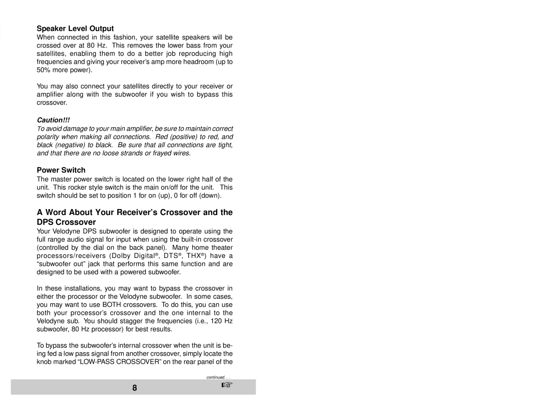
DPS-12, DPS-10 specifications
Velodyne Acoustics has established itself as a leader in the field of high-performance subwoofers, and their DPS-10 and DPS-12 models exemplify this commitment to excellence. Designed to deliver exceptional sound quality and precise audio reproduction, these subwoofers are popular among audiophiles and casual listeners alike.The Velodyne DPS-10 and DPS-12 subwoofers stand out due to their powerful digital power amplifiers. The DPS-10 features a robust 400-watt RMS amplifier, while the DPS-12 boasts an even more powerful 600-watt RMS amplifier. This ample power allows both models to produce deep, rich bass with astonishing clarity, making them ideal for a range of audio applications, from music playback to home theater systems.
One of the standout features of the DPS series is the incorporation of the Dynamic Drive System. This innovative technology ensures that the subwoofers can handle high output levels without distortion, providing a clean and accurate bass response. This system includes advanced algorithms that monitor the driver's performance in real time, adjusting the output to prevent over-excursion and maintain sound integrity.
Both models are equipped with a sophisticated Bass Equalization feature. This allows users to tailor the bass response according to their listening environment or personal preferences. The digital signal processing (DSP) capabilities enhance the overall audio experience by optimizing the low-frequency performance, adapting to different room acoustics, and minimizing the potential for unwanted resonances.
The physical design of the DPS-10 and DPS-12 is equally impressive. They feature a sleek, modern aesthetic that fits seamlessly into any home décor. The cabinets are constructed from high-quality materials to reduce vibration and resonance, ensuring that the sound quality remains pristine. The models also sport rear-firing ports that enhance bass response and provide added flexibility in placement within a room.
In addition to their impressive technical specifications, Velodyne's DPS-10 and DPS-12 subwoofers come equipped with user-friendly controls and connectivity options. The intuitive interface allows for easy adjustment of settings, while multiple input options make integration into existing audio systems straightforward.
In conclusion, the Velodyne Acoustics DPS-10 and DPS-12 subwoofers embody the perfect blend of power, precision, and flexibility. Their advanced technologies and design features make them an excellent choice for anyone seeking to enhance their audio experience, whether for music, movies, or gaming. With these subwoofers, Velodyne continues to set high standards for audio performance.

