Dutchwest
Flue Liner |
| |
Extend Chimney Con- | Damper | |
nector to the First Tile of | ||
Plate is | ||
the Flue Liner | ||
Removed | ||
| ||
| or Locked | |
Observe | in Open | |
Position | ||
Miniumum Clearances |
| |
| Close Off | |
| the Damper | |
| Opening with | |
| Sheet Metal | |
ST797 | and Sealant |
Fig. 8 The connector passes through the fireplace to enter flue. Special Fireplace Adapter Kits to simplify fireplace instal- lations are available from your local dealer.
Wall Pass-Throughs
Whenever possible, design your installation so the con- nector does not pass through a combustible wall. If you must use a wall
Accessories are available for use as wall pass- throughs. If using one of these, make sure it has been tested and listed for use as a wall
A
dealer or your local building inspector can provide de- tails of other approved methods of passing a chimney connector through a combustible wall.
DO NOT CONNECT THE HEATER TO ANY AIR DIS- TRIBUTION DUCT OR SYSTEM.
457 mm (18”) Empty Space All Around the Chimney Connector
Sheet Metal Cover (One side only)
ST421
Fig. 9 Hollow wall pass-through.
Hearths
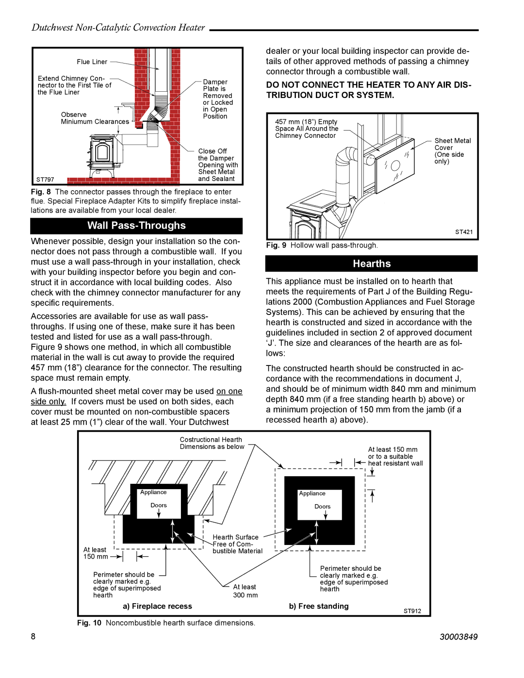
This appliance must be installed on to hearth that meets the requirements of Part J of the Building Regu- lations 2000 (Combustion Appliances and Fuel Storage Systems). This can be achieved by ensuring that the hearth is constructed and sized in accordance with the guidelines included in section 2 of approved document ‘J’. The size and clearances of the hearth are as fol- lows:
The constructed hearth should be constructed in ac- cordance with the recommendations in document J, and should be of minimum width 840 mm and minimum depth 840 mm (if a free standing hearth b) above) or a minimum projection of 150 mm from the jamb (if a recessed hearth a) above).
|
|
|
|
|
|
|
| Costructional Hearth |
|
|
|
|
|
|
|
|
|
|
|
| ||
|
|
|
|
|
|
|
| Dimensions as below |
|
|
|
|
|
|
|
|
| At least 150 mm | ||||
|
|
|
|
|
|
|
|
|
|
|
|
|
|
|
|
|
|
|
| |||
|
|
|
|
|
|
|
|
|
|
|
|
|
|
|
|
|
|
|
| or to a suitable | ||
|
|
|
|
| Appliance |
|
|
|
|
|
|
|
|
|
|
| heat resistant wall | |||||
|
|
|
|
|
|
|
|
|
|
|
|
|
|
|
|
|
|
| ||||
|
|
|
|
|
|
|
|
|
|
|
|
|
|
|
|
|
|
| ||||
|
|
|
|
|
|
| Appliance |
|
|
| ||||||||||||
|
|
|
|
|
| |||||||||||||||||
|
|
|
|
|
|
| Doors |
|
| Doors |
|
|
| |||||||||
|
|
|
|
|
|
|
|
|
|
|
| |||||||||||
|
|
|
|
|
|
|
|
| Hearth Surface |
|
|
|
|
|
|
|
|
|
|
|
| |
|
|
|
|
|
|
|
|
|
|
|
|
|
|
|
|
|
|
|
|
| ||
At least |
|
|
|
|
| Free of Com- |
|
|
|
|
|
|
|
|
|
|
|
| ||||
|
|
|
| bustible Material |
|
|
|
|
|
|
|
|
|
|
|
| ||||||
150 mm |
|
|
|
|
|
|
|
| Perimeter should be | |||||||||||||
|
|
|
|
|
|
|
| |||||||||||||||
| Perimeter should be |
|
| |||||||||||||||||||
|
|
| clearly marked e.g. | |||||||||||||||||||
| clearly marked e.g. |
| At least | edge of superimposed | ||||||||||||||||||
| edge of superimposed |
| hearth |
|
|
| ||||||||||||||||
| hearth |
| 300 mm |
|
|
|
|
|
|
|
|
|
|
|
| |||||||
|
|
|
| a) Fireplace recess |
|
| b) Free standing |
|
| ST912 | ||||||||||||
|
|
|
|
|
|
|
|
|
|
|
|
|
|
|
|
|
|
|
|
|
| |
Fig. 10 Noncombustible hearth surface dimensions. |
|
|
|
|
|
|
|
|
|
|
|
| ||||||||||
8 | 30003849 |
