electrical connection
This appliance must be connected to a grounded, metallic permanent wiring sys- tem or a ground connector should be connected to the ground terminal or wire lead on the cooktop.
This appliance is manufactured with a frame connected, green or bare ground wire. Connect the cooktop cable to the junction box through the CSA or
CONNECT WITH COPPER WIRE ONLY
✓ The flexible (4’) armoured cable should be connected directly to the junction box. |
✓ Do not cut the conduit. |
✓ A CSA or |
✓ Do not ground to a gas pipe. |
✓ Do not have a fuse in the grounding or neutral circuit. |
✓ Fuse both supply (phase) lines. |
![]() WARNING
WARNING
TO AVOID ELECTRICAL SHOCK HAZARD, BEFORE INSTALLING THE APPLIANCE, SWITCH POWER OFF AT THE SERVICE PANEL AND LOCK THE PANEL TO PREVENT THE POWER F R O M B E I N G S W I T C H E D O N ACCIDENTALLY.
power supply
✓ A time delay fuse or circuit breaker is recommended. |
✓ Connect directly to the fused disconnect (or circuit breaker box) through flexible, |
armored or |
✓ If codes permit and a separate grounding wire is used, it is recommended that a |
qualified electrician determine that the grounding path and wire gauge is in |
accordance with local codes. |
This appliance does not require a neutral connection. If the appliance is to be completely enclosed in a cabinet, feed the appliance cable through the opening in the cabinet. Make the electrical connection following the appropriate steps for your installation.
1. | Disconnect the power supply. |
2. | Remove the junction box cover. |
3. | Connect the cooktop cable to the junction box through the CSA or |
| connector. |
4. | Connect the two black wires together with |
5. | Connect the two red wires together with |
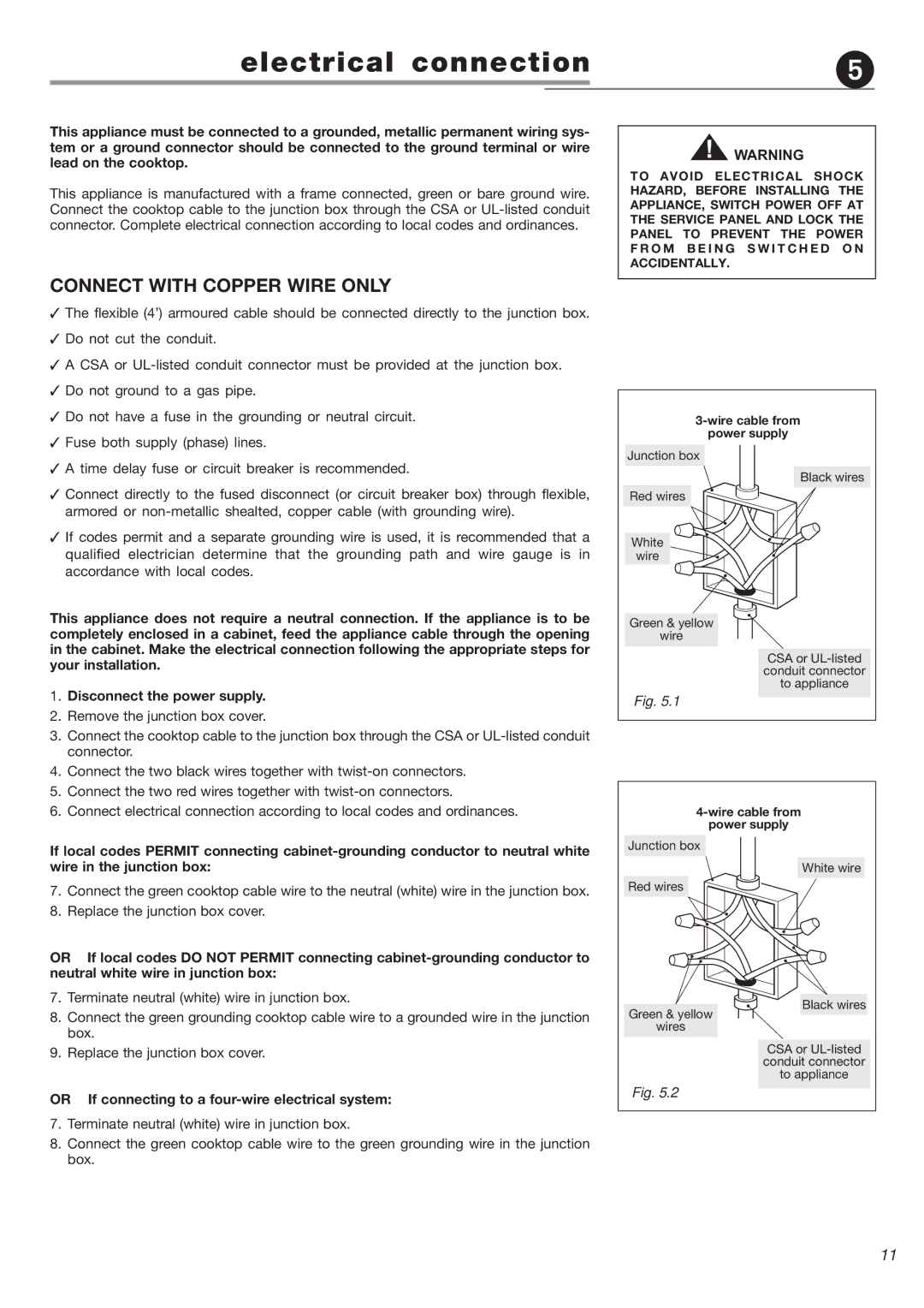
Junction box
Red wires
White
wire
Green & yellow
wire
Fig. 5.1
Black wires
CSA or
6. Connect electrical connection according to local codes and ordinances. |
power supply
If local codes PERMIT connecting
7.Connect the green cooktop cable wire to the neutral (white) wire in the junction box.
8.Replace the junction box cover.
OR If local codes DO NOT PERMIT connecting
7.Terminate neutral (white) wire in junction box.
8.Connect the green grounding cooktop cable wire to a grounded wire in the junction box.
9.Replace the junction box cover.
OR If connecting to a four-wire electrical system:
7.Terminate neutral (white) wire in junction box.
8.Connect the green cooktop cable wire to the green grounding wire in the junction box.
Junction box
Red wires
Green & yellow
wires
Fig. 5.2
White wire
Black wires
CSA or
11