MICROPHONE,
SUB INPUT SECTION
LINE 4 IN
9L ![]()
![]() R
R
|
| MIC |
10 |
|
|
| ||
|
| |
11 | MIN | MAX |
|
| |
| MIN | MAX |
| EQ |
|
| HI |
|
12 | +16dB | |
| LOW |
|
| +16dB |
EFFECT
13�
� | OFF POST |
CUE
14
OFFON
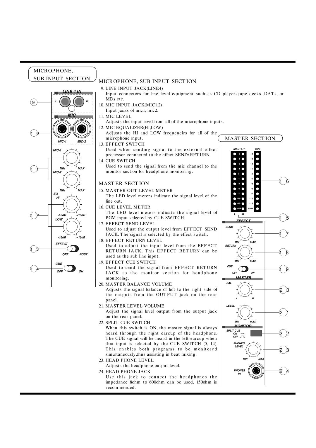
MICROPHONE, SUB INPUT SECTION
9.LINE INPUT JACK(LINE4)
Input connectors for line level equipment such as CD players,tape decks ,DATs, or MDs etc.
10.MIC INPUT JACK(MIC1,2) Input jacks of mic1, mic2.
11.MIC LEVEL
Adjusts the input level from all of the microphone inputs.
12.MIC EQUALIZER(HI,LOW)
Adjusts the HI and LOW frequencies for all of the
microphone input. | MASTER SECTION | ||||
13. EFFECT SWITCH |
|
|
|
|
|
Used when sending signal to the external effect |
| MASTER |
| CUE |
|
processor connected to the effect SEND/RETURN. | +8 | +8 |
|
| |
+5 | +5 |
|
| ||
14. CUE SWITCH |
|
| |||
+3 | +3 |
|
| ||
Used to send the signal from the mic channel to the |
|
| |||
+1 | +1 |
|
| ||
monitor section for headphone monitoring. |
|
| |||
|
|
|
|
| |
| 0 |
| 0 |
|
MASTER SECTION |
| 16 | ||
| ||||
|
| |||
15. MASTER OUT LEVEL METER |
|
| ||
|
| |||
The LED level meters indicate the signal level of the |
|
| ||
|
| |||
line out. |
|
| ||
|
| |||
16. CUE LEVEL METER |
|
| ||
POWER |
| POWER |
| |
The LED level meters indicate the signal level of | L | R |
| 15 |
PGM input selected by CUE SWITCH. | EFFECT | |||
17. EFFECT SEND LEVEL |
| |||
SEND |
|
|
| |
Used to adjust the output level from EFFECT SEND |
|
|
| |
|
|
| 17 | |
JACK. The signal is selected by the effect switch. |
|
|
| |
18. EFFECT RETURN LEVEL | MIN |
| MAX |
|
Used to adjust the input level from the EFFECT | RETURN |
|
|
|
RETURN JACK. This EFFECT RETURN can be |
|
|
| 18 |
used as the sub line input. |
|
|
| |
|
|
|
| |
19. EFFECT CUE SWITCH | MIN |
| MAX |
|
|
|
|
| |
Used to send the signal from EFFECT RETURN | CUE |
|
| 19 |
|
|
| ||
JACK to the monitor section for headphone | OFF |
| ON | |
|
| |||
monitoring. | MASTER |
| ||
20. MASTER BALANCE VOLUME | BAL |
|
|
|
|
|
|
| |
Adjusts the signal balance of left to the right side of |
|
|
| 20 |
the outputs from the OUTPUT jack on the rear |
|
|
|
|
panel. | L |
| R |
|
|
|
|
| |
21. MASTER LEVEL VOLUME | LEVEL |
|
|
|
Adjust the signal level output from the output jack |
|
|
| 21 |
on the rear panel. |
|
|
|
|
22. SPLIT CUE SWITCH | MIN |
| MAX |
|
When this switch is ON, the master signal is always | MONITOR |
| ||
SPLIT CUE |
|
|
| |
heard through the right earcup of the headphone. |
|
| 22 | |
ON |
|
| ||
The CUE signal will be heard in the left earcup when | OFF |
|
|
|
|
|
|
| |
that input is selected by the CUE SWITCH (5, 14). | PHONES |
|
| |
This enables both programs to be monitored | LEVEL |
| 23 | |
|
|
| ||
simultaneously,thus assisting in beat mixing. |
|
|
|
|
23. HEAD PHONE LEVEL |
| MIN |
| MAX |
|
|
|
| |
Adjusts the headphone output level. |
|
|
| 24 |
24. HEAD PHONE JACK | PHONES |
| ||
IN |
|
| ||
Use this jack to connect the headphones the |
|
|
| |
|
|
|
| |
impedance 8ohm to 600ohm can be used, 150ohm is |
|
|
|
|
recommended. |
|
|
|
|