Getting Started
Rear and Side View of the Product
ENGLISH
Item | Description |
|
|
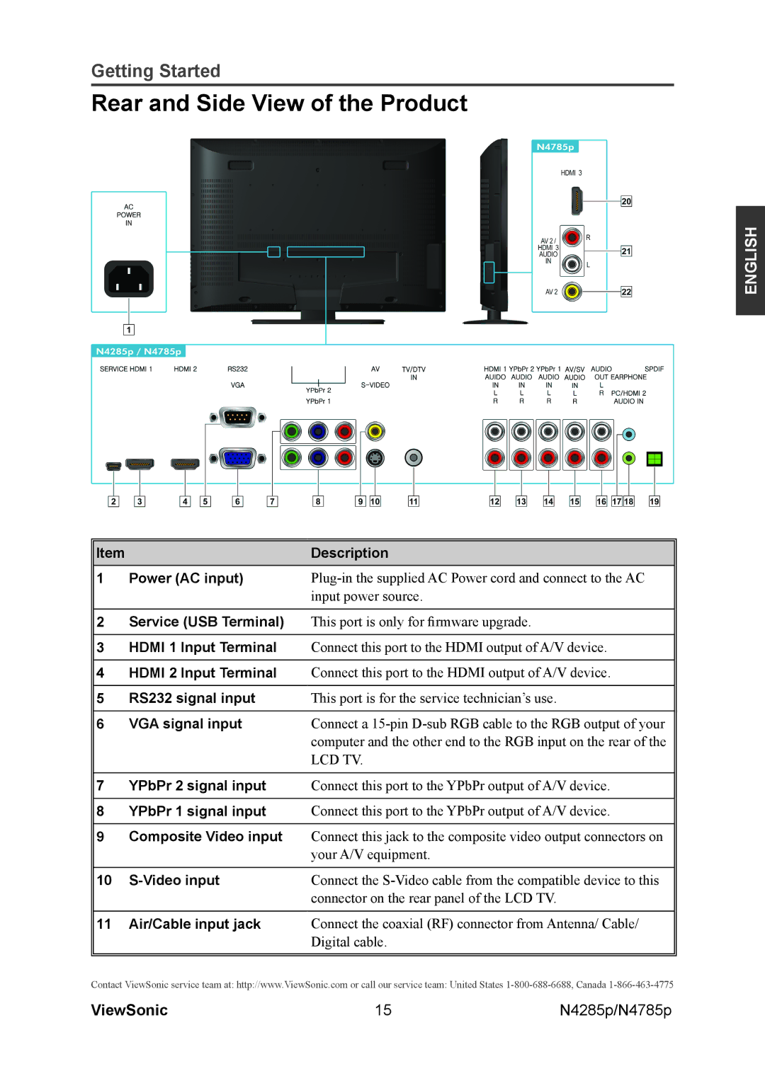
1 Power (AC input) | |
| input power source. |
2Service (USB Terminal) This port is only for firmware upgrade.
3HDMI 1 Input Terminal Connect this port to the HDMI output of A/V device.
4HDMI 2 Input Terminal Connect this port to the HDMI output of A/V device.
5 | RS232 signal input | This port is for the service technician’s use. |
|
|
|
6 | VGA signal input | Connect a |
|
| computer and the other end to the RGB input on the rear of the |
|
| LCD TV. |
|
|
|
7 | YPbPr 2 signal input | Connect this port to the YPbPr output of A/V device. |
|
|
|
8 | YPbPr 1 signal input | Connect this port to the YPbPr output of A/V device. |
9Composite Video input Connect this jack to the composite video output connectors on your A/V equipment.
10 |
| Connect the |
|
| connector on the rear panel of the LCD TV. |
|
|
|
11 | Air/Cable input jack | Connect the coaxial (RF) connector from Antenna/ Cable/ |
|
| Digital cable. |
Contact ViewSonic service team at: http://www.ViewSonic.com or call our service team: United States
ViewSonic | 15 | N4285p/N4785p |