Complete Hardware Guide for EX3200 and EX4200 Ethernet Switches
■Rear Panel of an EX3200 Switch on page 9
■Rear Panel of an EX4200 Switch on page 11
Installing a Fan Tray in an EX3200 or EX4200 Switch
EX3200 and EX4200 switches have a single
Before you begin installing a fan tray in an EX3200 or EX4200 switch, ensure that you have taken the necessary precautions to prevent ESD damage (see “Prevention of Electrostatic Discharge Damage on EX Series Switches” on page 236).
Ensure that you have the following parts and tools available to install a fan tray in an EX3200 or EX4200 switch chassis:
■Electrostatic discharge (ESD) grounding strap
■Phillips (+) screwdriver, number 2
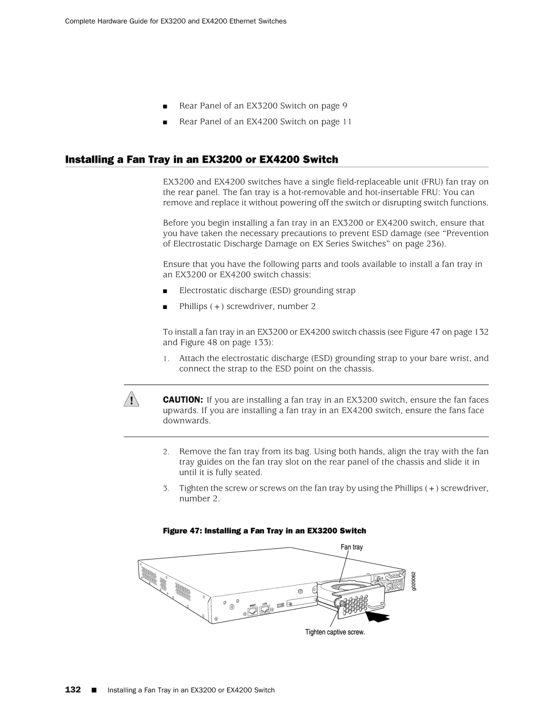
To install a fan tray in an EX3200 or EX4200 switch chassis (see Figure 47 on page 132 and Figure 48 on page 133):
1.Attach the electrostatic discharge (ESD) grounding strap to your bare wrist, and connect the strap to the ESD point on the chassis.
CAUTION: If you are installing a fan tray in an EX3200 switch, ensure the fan faces upwards. If you are installing a fan tray in an EX4200 switch, ensure the fans face downwards.
2.Remove the fan tray from its bag. Using both hands, align the tray with the fan tray guides on the fan tray slot on the rear panel of the chassis and slide it in until it is fully seated.
3.Tighten the screw or screws on the fan tray by using the Phillips (+) screwdriver, number 2.