Complete Hardware Guide for EX3200 and EX4200 Ethernet Switches
master boot record. See the documentation for your USB flash drive for information on how your USB flash drive is formatted.
Related Topics ■ See Rear Panel of an EX2200 Switch for port location.
■ See Rear Panel of an EX3200 Switch on page 9 for port location. ■ See Rear Panel of an EX4200 Switch on page 11 for port location.
■ See Switch Fabric and Routing Engine (SRE) Module in an EX8208 Switch for port location.
■ See Routing Engine (RE) Module in an EX8216 Switch for port location.
■ Booting an EX Series Switch Using a Software Package Stored on a USB Flash Drive
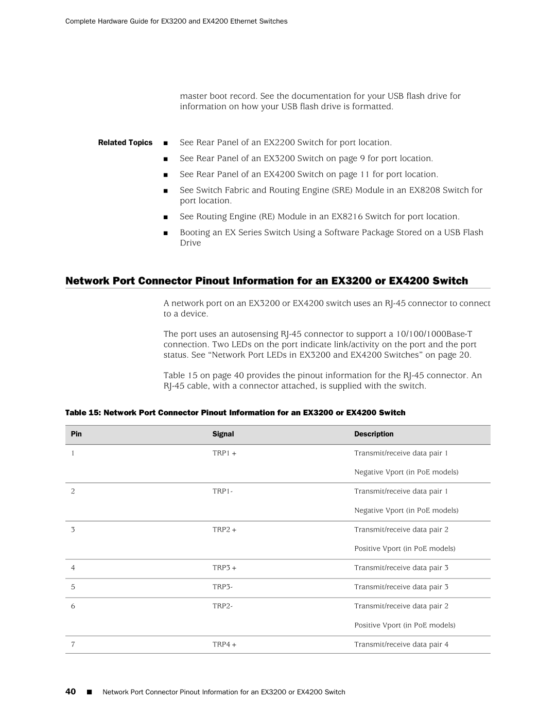
Network Port Connector Pinout Information for an EX3200 or EX4200 Switch
A network port on an EX3200 or EX4200 switch uses an
The port uses an autosensing
Table 15 on page 40 provides the pinout information for the
Table 15: Network Port Connector Pinout Information for an EX3200 or EX4200 Switch
Pin | Signal | Description |
1 | TRP1+ | Transmit/receive data pair 1 |
|
| Negative Vport (in PoE models) |
2 | TRP1- | Transmit/receive data pair 1 |
|
| Negative Vport (in PoE models) |
3 | TRP2+ | Transmit/receive data pair 2 |
|
| Positive Vport (in PoE models) |
4 | TRP3+ | Transmit/receive data pair 3 |
5 | TRP3- | Transmit/receive data pair 3 |
6 | TRP2- | Transmit/receive data pair 2 |
|
| Positive Vport (in PoE models) |
7 | TRP4+ | Transmit/receive data pair 4 |
40■ Network Port Connector Pinout Information for an EX3200 or EX4200 Switch