Chapter 10: Installing Switch Components
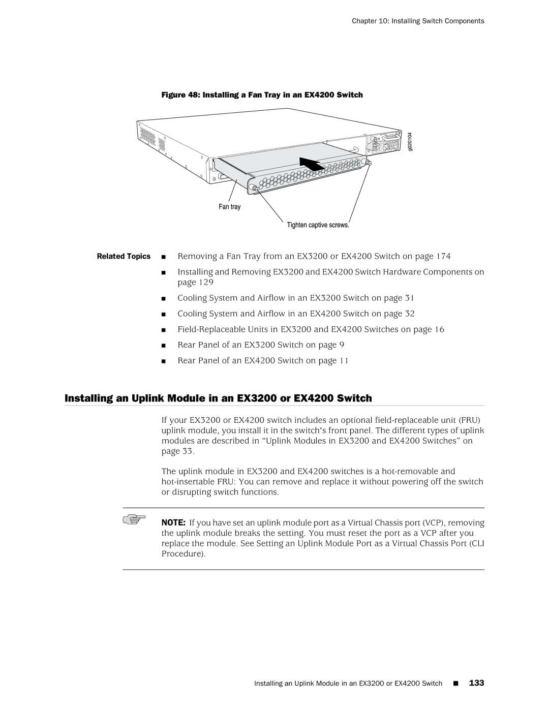
Figure 48: Installing a Fan Tray in an EX4200 Switch
Related Topics ■ Removing a Fan Tray from an EX3200 or EX4200 Switch on page 174
■Installing and Removing EX3200 and EX4200 Switch Hardware Components on page 129
■Cooling System and Airflow in an EX3200 Switch on page 31
■Cooling System and Airflow in an EX4200 Switch on page 32
■
■Rear Panel of an EX3200 Switch on page 9
■Rear Panel of an EX4200 Switch on page 11
Installing an Uplink Module in an EX3200 or EX4200 Switch
If your EX3200 or EX4200 switch includes an optional
The uplink module in EX3200 and EX4200 switches is a
NOTE: If you have set an uplink module port as a Virtual Chassis port (VCP), removing the uplink module breaks the setting. You must reset the port as a VCP after you replace the module. See Setting an Uplink Module Port as a Virtual Chassis Port (CLI Procedure).