Complete Hardware Guide for EX3200 and EX4200 Ethernet Switches
Before you begin connecting a Virtual Chassis cable to an EX4200 switch, ensure that you have taken the necessary precautions to prevent ESD damage (see “Prevention of Electrostatic Discharge Damage on EX Series Switches” on page 236).
Ensure that you have the following parts and tools available to connect a Virtual
Chassis cable to an EX4200 switch:
■Electrostatic discharge (ESD) grounding strap
■
NOTE: If you order Virtual Chassis cables separately, you must reuse the locking covers provided with the original cable or order Virtual Chassis cable locking covers also separately.
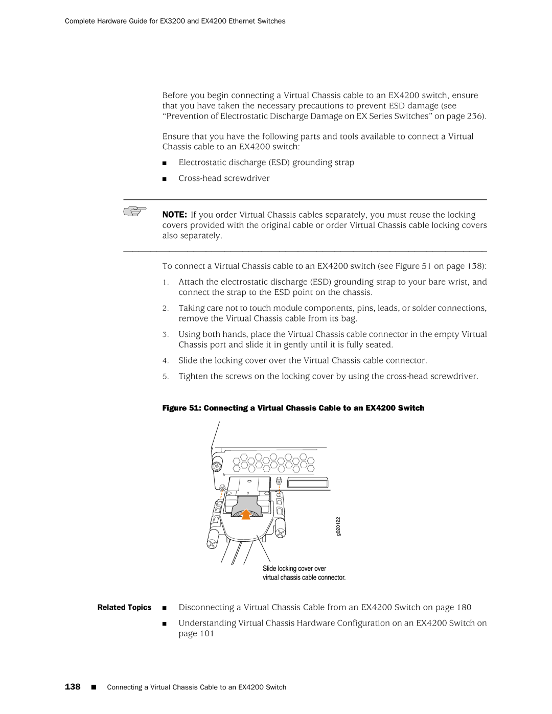
To connect a Virtual Chassis cable to an EX4200 switch (see Figure 51 on page 138):
1.Attach the electrostatic discharge (ESD) grounding strap to your bare wrist, and connect the strap to the ESD point on the chassis.
2.Taking care not to touch module components, pins, leads, or solder connections, remove the Virtual Chassis cable from its bag.
3.Using both hands, place the Virtual Chassis cable connector in the empty Virtual Chassis port and slide it in gently until it is fully seated.
4.Slide the locking cover over the Virtual Chassis cable connector.
5.Tighten the screws on the locking cover by using the
Figure 51: Connecting a Virtual Chassis Cable to an EX4200 Switch
Related Topics ■ Disconnecting a Virtual Chassis Cable from an EX4200 Switch on page 180
■Understanding Virtual Chassis Hardware Configuration on an EX4200 Switch on page 101