Chapter 5: Mounting and Clearance Requirements
Related Topics ■ Clearance Requirements for Airflow and Hardware Maintenance for EX3200 and EX4200 Switches on page 91
■
■Mounting an EX3200 or EX4200 Switch on a Desk or Other Level Surface on page 117
■Mounting an EX3200 or EX4200 Switch on a Wall on page 125
Clearance Requirements for Airflow and Hardware Maintenance for EX3200 and EX4200 Switches
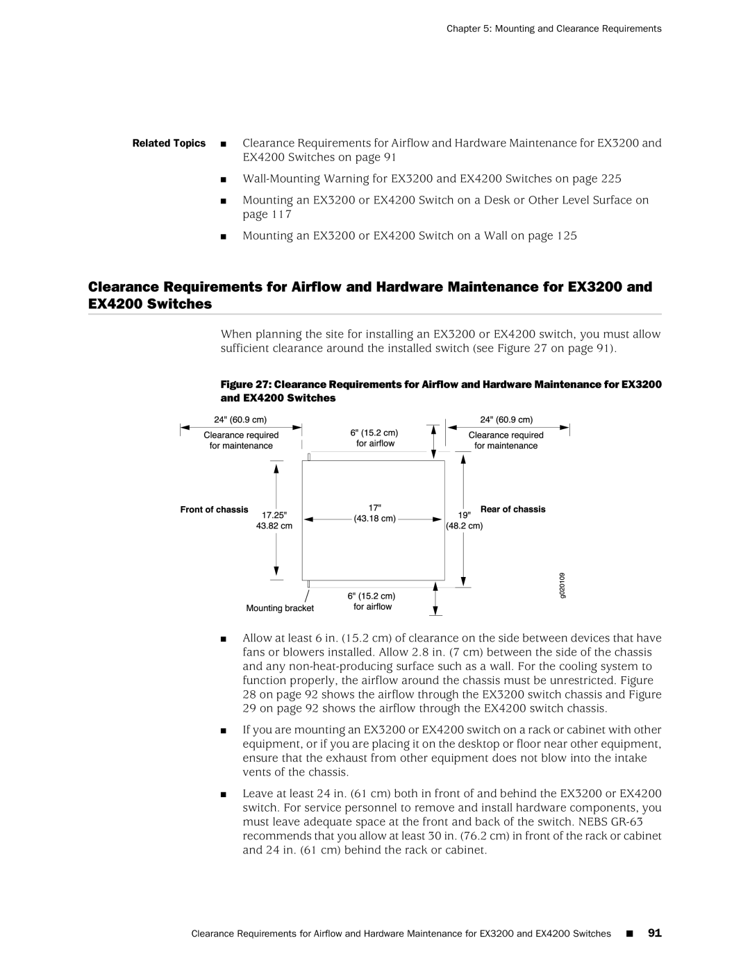
When planning the site for installing an EX3200 or EX4200 switch, you must allow sufficient clearance around the installed switch (see Figure 27 on page 91).
Figure 27: Clearance Requirements for Airflow and Hardware Maintenance for EX3200 and EX4200 Switches
■Allow at least 6 in. (15.2 cm) of clearance on the side between devices that have fans or blowers installed. Allow 2.8 in. (7 cm) between the side of the chassis and any
■If you are mounting an EX3200 or EX4200 switch on a rack or cabinet with other equipment, or if you are placing it on the desktop or floor near other equipment, ensure that the exhaust from other equipment does not blow into the intake vents of the chassis.
■Leave at least 24 in. (61 cm) both in front of and behind the EX3200 or EX4200 switch. For service personnel to remove and install hardware components, you must leave adequate space at the front and back of the switch. NEBS
Clearance Requirements for Airflow and Hardware Maintenance for EX3200 and EX4200 Switches ■ 91