Chapter 10: Installing Switch Components
NOTE: The handle on the 320 W AC power supply is at the bottom of the power supply faceplate, while the handle on the 600 W and the 930 W AC power supplies is at the top of the faceplate. The handle on the 190 W DC power supply runs across the faceplate.
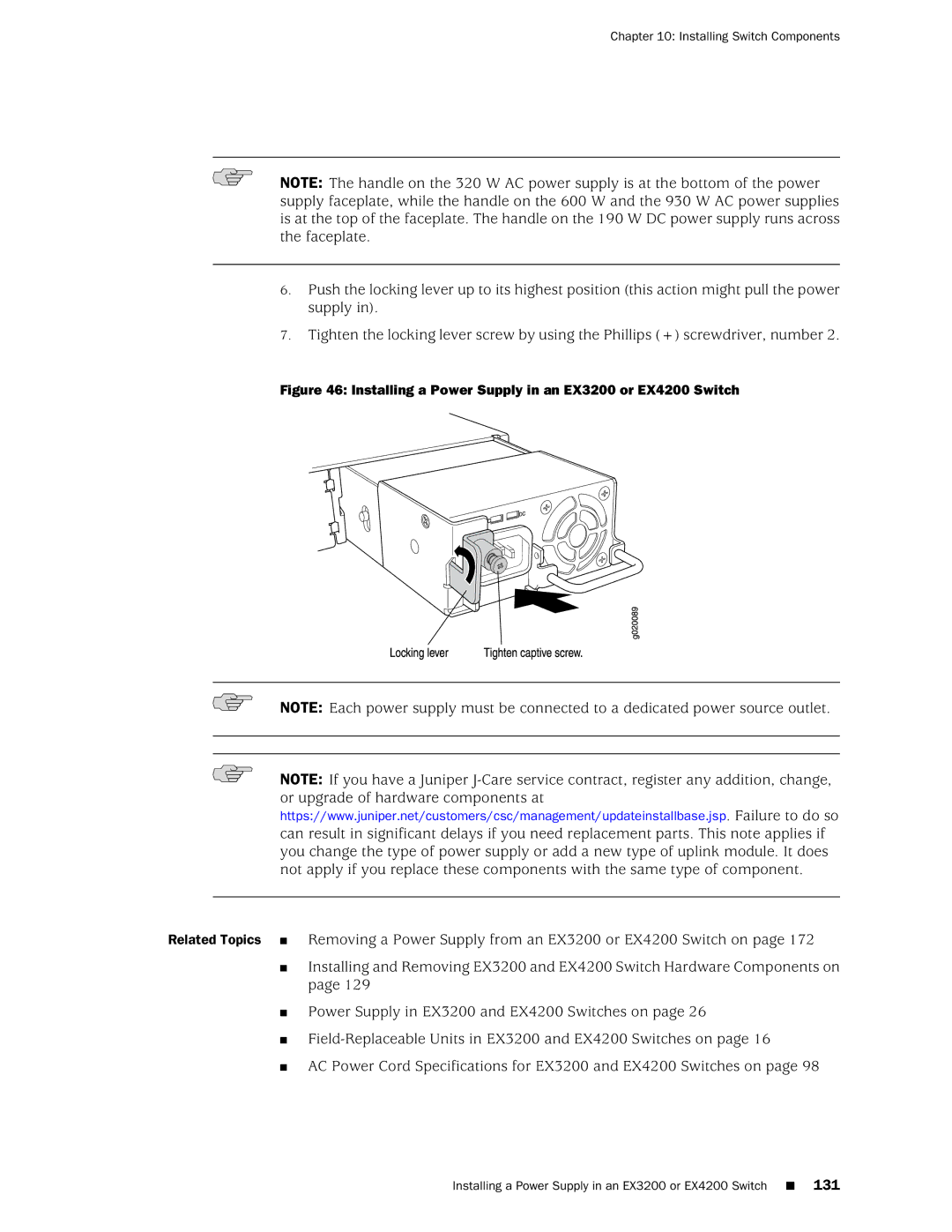
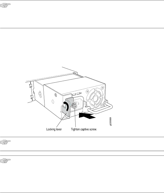
6.Push the locking lever up to its highest position (this action might pull the power supply in).
7.Tighten the locking lever screw by using the Phillips (+) screwdriver, number 2.
Figure 46: Installing a Power Supply in an EX3200 or EX4200 Switch
NOTE: Each power supply must be connected to a dedicated power source outlet.
NOTE: If you have a Juniper
Related Topics ■ Removing a Power Supply from an EX3200 or EX4200 Switch on page 172
■Installing and Removing EX3200 and EX4200 Switch Hardware Components on page 129
■Power Supply in EX3200 and EX4200 Switches on page 26
■
■AC Power Cord Specifications for EX3200 and EX4200 Switches on page 98