Complete Hardware Guide for EX3200 and EX4200 Ethernet Switches
WARNING: When mounted in a vertical position, an EX3200 or EX4200 switch must be oriented with the front panel of the chassis pointing down in order to ensure proper airflow and meet safety requirements in the event of a fire.
NOTE: For easier lifting, install any additional power supplies only after you mount the switch on the wall.
To mount the switch on a wall:
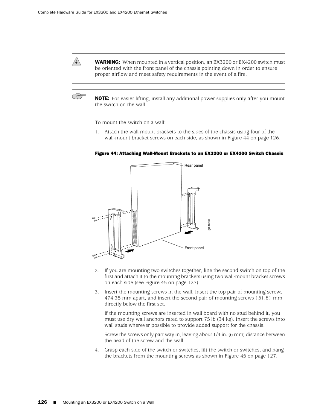
1.Attach the
Figure 44: Attaching Wall-Mount Brackets to an EX3200 or EX4200 Switch Chassis
 Rear panel
g020200
Front panel
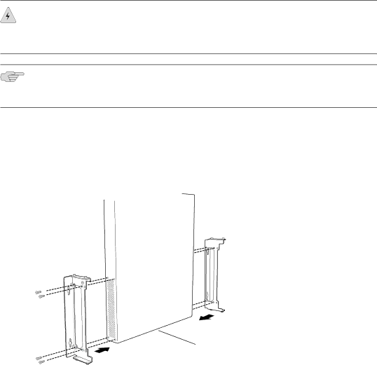
2.If you are mounting two switches together, line the second switch on top of the first and attach it to the mounting brackets using two
3.Insert the mounting screws in the wall. Insert the top pair of mounting screws 474.35 mm apart, and insert the second pair of mounting screws 151.81 mm directly below the first set.
If the mounting screws are inserted in wall board with no stud behind it, you must use dry wall anchors rated to support 75 lb (34 kg). Insert the screws into wall studs wherever possible to provide added support for the chassis.
Screw the screws only part way in, leaving about 1/4 in. (6 mm) distance between the head of the screw and the wall.
4.Grasp each side of the switch or switches, lift the switch or switches, and hang the brackets from the mounting screws as shown in Figure 45 on page 127.