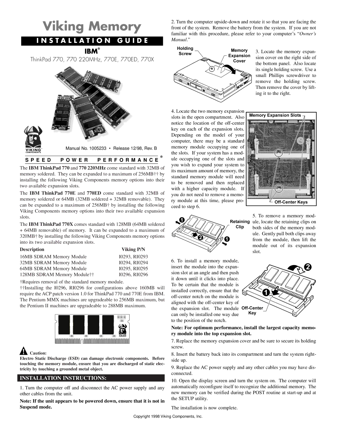
Viking Memory
I N S T A L L A T I O N G U I D E
2.Turn the computer
IBM®
ThinkPad 770, 770 220MHz, 770E, 770ED, 770X
Manual No. 1005233 • Release 12/98, Rev. B
®
S P E E D P O W E R P E R F O R M A N C E
The IBM ThinkPad 770 and 770 220MHz come standard with 32MB of memory soldered. They can be expanded to a maximum of 256MB†† by installing the following Viking Components memory options into their two available expansion slots.
The IBM ThinkPad 770E and 770ED come standard with 32MB of memory soldered or 64MB (32MB soldered + 32MB removable). They can be expanded to a maximum of 256MB† by installing the following Viking Components memory options into their two available expansion slots.
The IBM ThinkPad 770X comes standard with 128MB (64MB soldered
+64MB removable) of memory. It can be expanded to a maximum of 320MB† by installing the following Viking Components memory options into its two available expansion slots.
Description | Viking P/N |
16MB SDRAM Memory Module | I0293, RI0293 |
32MB SDRAM Memory Module | I0294, RI0294 |
64MB SDRAM Memory Module | I0295, RI0295 |
128MB SDRAM Memory Module†† | I0296, RI0296 |
†Requires removal of the standard memory module.
††Installing the I0296, RI0296 for configurations above 160MB will require the ACP patch version 1.0 for ThinkPad 770 and 770E from IBM. The Pentium MMX machines are upgradeable to 256MB maximum, but the Pentium II machines are upgradeable to 288MB maximum.
4.Locate the two memory expansion slots in the open compartment. Also notice the location of the
6.To install a memory module, insert the module into the expan- sion slot at an angle and then push it down until it clicks into place. To be certain that the module is installed correctly, ensure that the
3.Locate the memory expan- sion cover on the right side of the bottom panel. Also locate its single holding screw. Use a small Phillips screwdriver to remove the holding screw. Then remove the cover by lift- ing it to the right.
5.To remove a memory mod- ule, locate the retaining clips on both sides of the memory mod- ule. Gently pull both clips away from the module, then lift the module out of its expansion slot.
![]() Caution:
Caution:
Electro Static Discharge (ESD) can damage electronic components. Before touching the memory module, ensure that you are discharged of static elec- tricity by touching a grounded metal object.
INSTALLATION INSTRUCTIONS:
1.Turn the computer off and disconnect the AC power supply and any other cables from the unit.
Note: If the unit appears to be powered down, ensure that it is not in Suspend mode.
Note: For optimum performance, install the largest capacity memo- ry module into the top expansion slot.
7.Replace the memory expansion cover and be sure to secure its holding screw.
8.Insert the battery back into its compartment and turn the system right- side up.
9.Replace the AC power supply and any other cables you may have dis- connected.
10.Open the display screen and turn the system on. The computer will automatically reconfigure itself to recognize the additional memory. The new memory can be verified during the POST routine at
The installation is now complete.
Copyright 1998 Viking Components, Inc.