
FD-8372 specifications
The Vivotek FD-8372 is a high-performance network camera designed to meet a wide range of surveillance needs in both indoor and outdoor environments. This sleek, compact device combines advanced technologies with user-friendly features, making it an ideal choice for businesses and security professionals alike.One of the standout features of the FD-8372 is its 2-Megapixel resolution, providing exceptional image quality and clarity for effective monitoring. This network camera supports H.264 and MJPEG compression formats, enabling efficient bandwidth usage and storage without compromising on image quality. With its progressive scan CMOS sensor, users can expect detailed and vibrant images even in varying lighting conditions.
Another significant aspect of the FD-8372 is its Wide Dynamic Range (WDR) technology. This feature allows the camera to capture clear images in environments with high contrast lighting, such as areas with both bright sunlight and deep shadows. The result is balanced imaging that enhances visibility and helps reduce the likelihood of blind spots during surveillance.
The FD-8372 is equipped with a built-in Infrared (IR) array that enables effective night vision capabilities. This functionality ensures that the camera can monitor areas in complete darkness, providing visibility up to 30 meters. The IR-cut filter also enhances image quality during the day, ensuring accurate color reproduction.
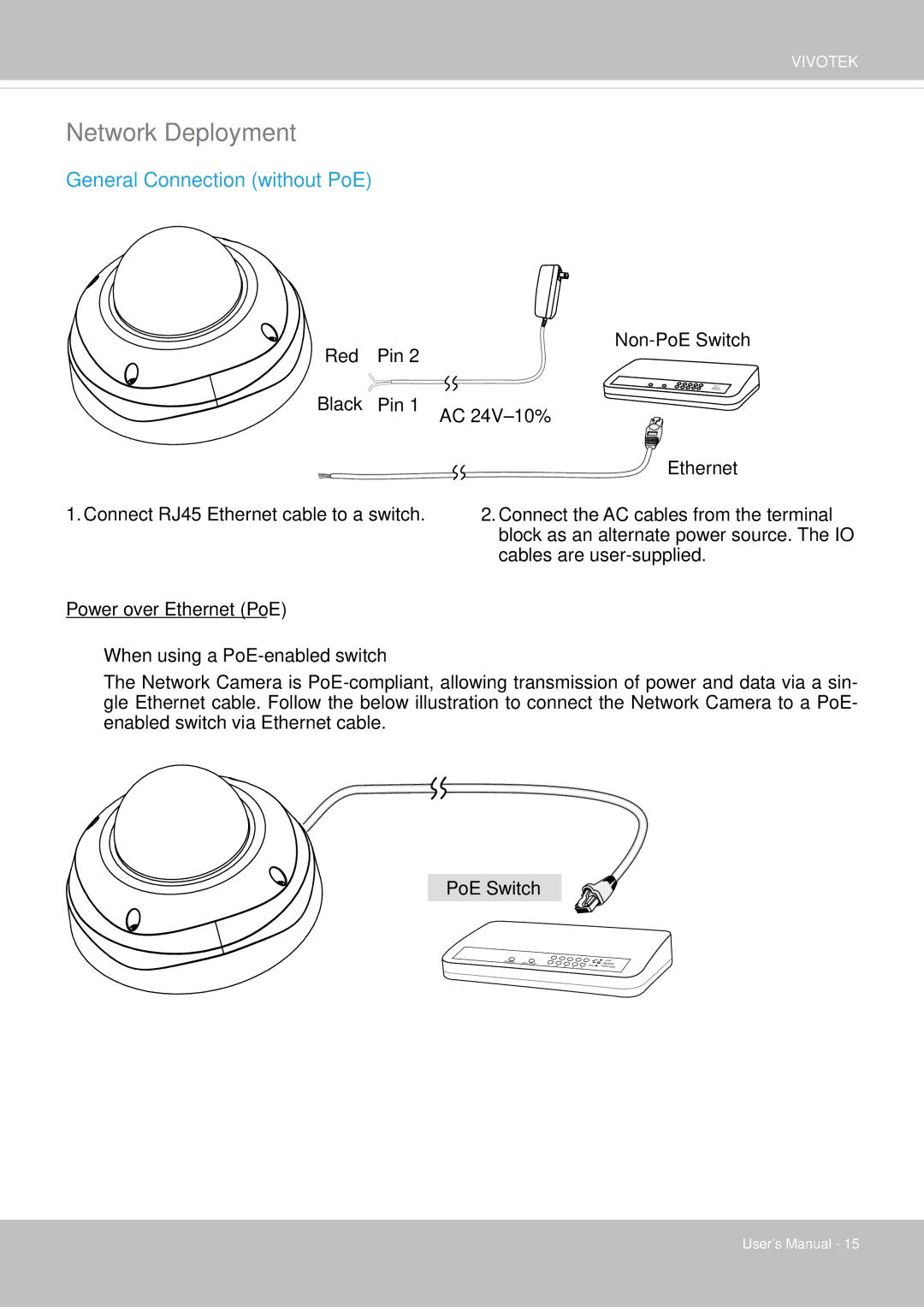
Additionally, the FD-8372 features PoE (Power over Ethernet) support, simplifying installation by allowing the camera to receive power and network connectivity through a single cable. This feature is particularly useful in locations where power outlets are scarce or difficult to access.
For enhanced reliability and ease of use, the FD-8372 comes with a weather-proof and vandal-proof housing, rated to IP66 standards. This ensures that the camera can withstand various environmental conditions, making it suitable for outdoor installation. The device also supports multiple streaming profiles, accommodating various user needs and allowing for simultaneous viewing on different devices.
The intuitive web interface and compatibility with Vivotek's VAST software platform further streamline setup and management. Users can easily access, control, and configure the camera remotely, enhancing the overall surveillance experience.
Lastly, the FD-8372 is designed with a focus on security, featuring built-in security mechanisms such as password protection, IP address filtering, and HTTPS encryption to safeguard sensitive surveillance data. Overall, the Vivotek FD-8372 is a robust, versatile solution for those seeking to enhance their security infrastructure with cutting-edge technology and reliable performance.