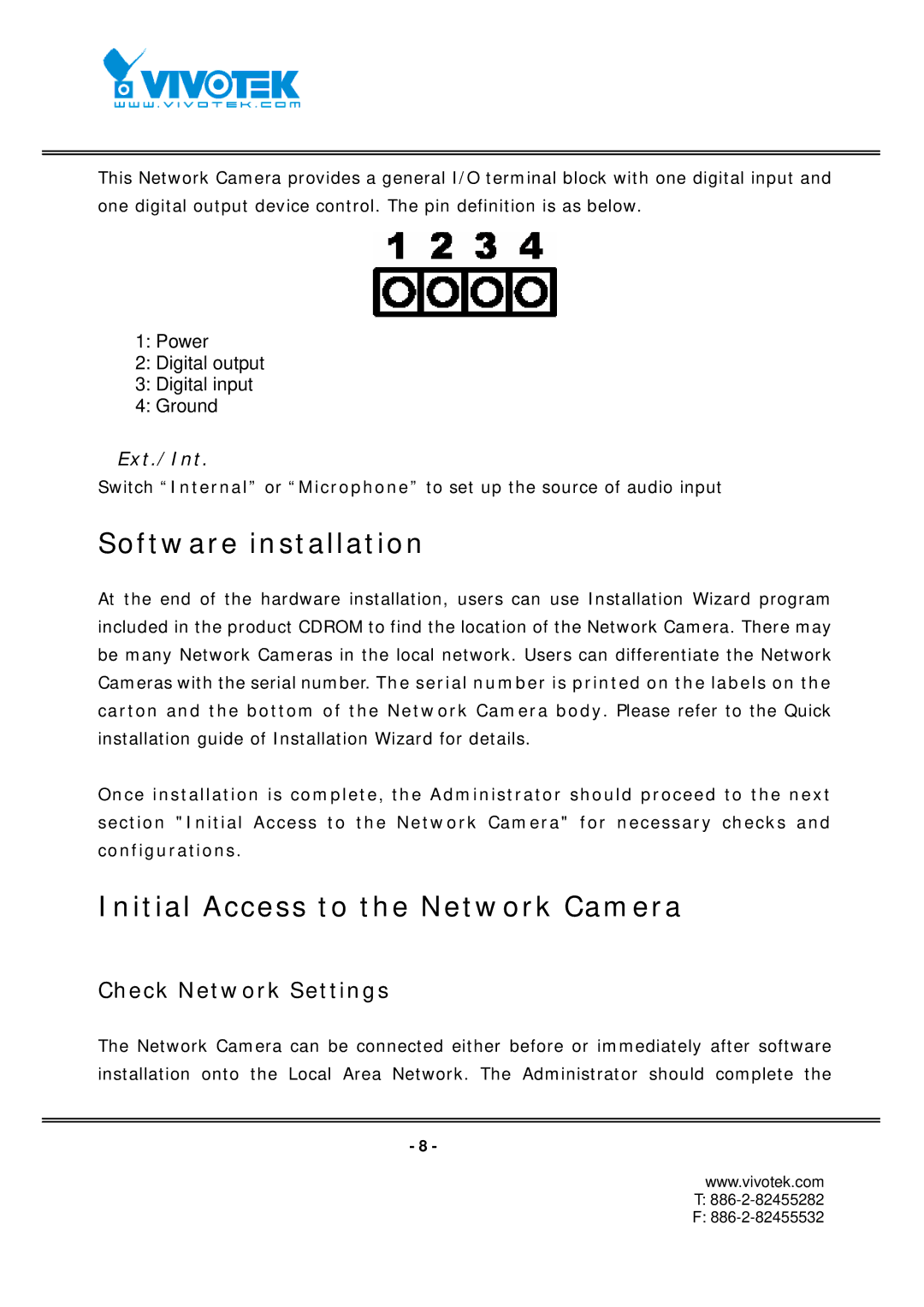
This Network Camera provides a general I/O terminal block with one digital input and one digital output device control. The pin definition is as below.
1:Power
2:Digital output
3:Digital input
4:Ground
Ext./Int.
Switch “Internal” or “Microphone” to set up the source of audio input
Software installation
At the end of the hardware installation, users can use Installation Wizard program included in the product CDROM to find the location of the Network Camera. There may be many Network Cameras in the local network. Users can differentiate the Network Cameras with the serial number. The serial number is printed on the labels on the carton and the bottom of the Network Camera body. Please refer to the Quick installation guide of Installation Wizard for details.
Once installation is complete, the Administrator should proceed to the next section "Initial Access to the Network Camera" for necessary checks and configurations.
Initial Access to the Network Camera
Check Network Settings
The Network Camera can be connected either before or immediately after software installation onto the Local Area Network. The Administrator should complete the
- 8 -
www.vivotek.com
T:
F: