INSTRUCTION MANUAL
CAR AMPLIFIERCA-115 CA-130
Thank you very much for purchasing TOA's Car Amplifier. To prolong the life of your amplifier by operating and using it correctly, please read this instruction manual carefully. The Car Amplifier described in this manual has a rated output of 15 W
SAFETY PRECAUTIONS
Be sure to read the instructions in this section carefully before use.
Make | sure to observe | the instructions | in | this manual as the conventions | of | ||
safety | symbols and | messages regarded | as very | important precautions | are | ||
included. |
|
|
|
|
|
| |
We also recommend | y ou keep this | instruction | manual | handy for future | |||
reference. |
|
|
|
|
|
| |
|
| Indicates a potentially hazardous | situation which, if | ||||
mishandled, could result in death or serious
personal injury.
Do not install the unit in the following locations to avoid a traffic accident and personal injury:
•Locations which block the driving of a car.
•Locations where the unit contacts the user's body or cloth when getting on or down the car.
Indicatesa potentiallyhazardous situationwhich, if mishandled, could result in moderate or minor personal injury, and/or propertydamage.
Connect the power cord as instructed below. Failure to do so could result in electric shock or a failure of the amplifier or car.
•Connect the red cord directly to the positive ![]() terminal of the battery, and the blue cord to the negative
terminal of the battery, and the blue cord to the negative![]() terminal.
terminal.
•Insulate joints between the power cord and battery terminal with the vinyl tape.
TOA Corporation
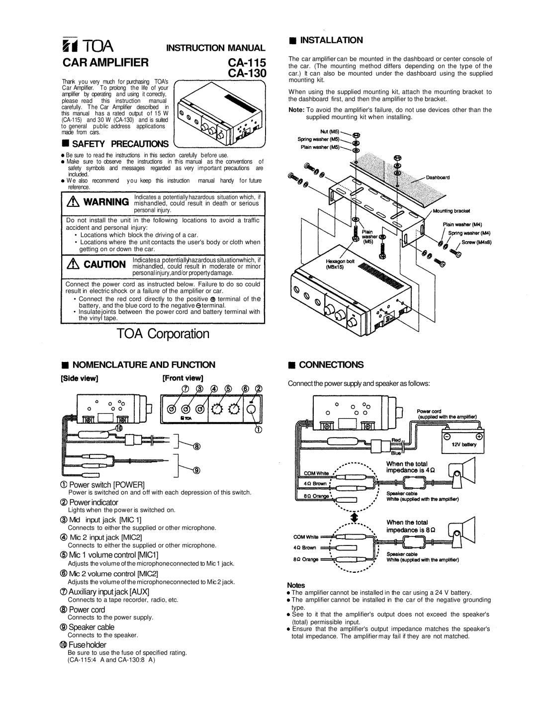
NOMENCLATURE AND FUNCTION
Power switch [POWER]
Power is switched on and off with each depression of this switch.
Power indicator
Lights when the power is switched on.
Mid input jack [MIC 1]
Connects to either the supplied or other microphone.
Mic 2 input jack [MIC2]
Connects to either the supplied or other microphone.
Mic 1 volume control [MIC1]
Adjusts the volume of the microphoneconnected to Mic 1 jack.
Mic 2 volume control [MIC2]
Adjusts the volume of the microphoneconnected to Mic 2 jack.
Auxiliary input jack [AUX]
Connects to a tape recorder, radio, etc.
Power cord
Connects to the power supply.
Speaker cable
Connects to the speaker.
Fuseholder
INSTALLATION
The car amplifier can be mounted in the dashboard or center console of the car. (The mounting method differs depending on the type of the car.) It can also be mounted under the dashboard using the supplied mounting kit.
When using the supplied mounting kit, attach the mounting bracket to the dashboard first, and then the amplifier to the bracket.
Note: To avoid the amplifier's failure, do not use devices other than the supplied mounting kit when installing.
CONNECTIONS
Connect the power supply and speaker as follows:
Notes
The amplifier cannot be installed in the car using a 24 V battery.
The amplifier cannot be installed in the car of the negative grounding type.
See to it that the amplifier's output does not exceed the speaker's (total) permissible input.
Ensure that the amplifier's output impedance matches the speaker's total impedance. The amplifier may fail if they are not matched.
Be sure to use the fuse of specified rating.